STLCutter 2 - Day 1
I'd left the plans for the CNC machine with Keith, who told me that they'd made the main frame before my first day. And there it was!
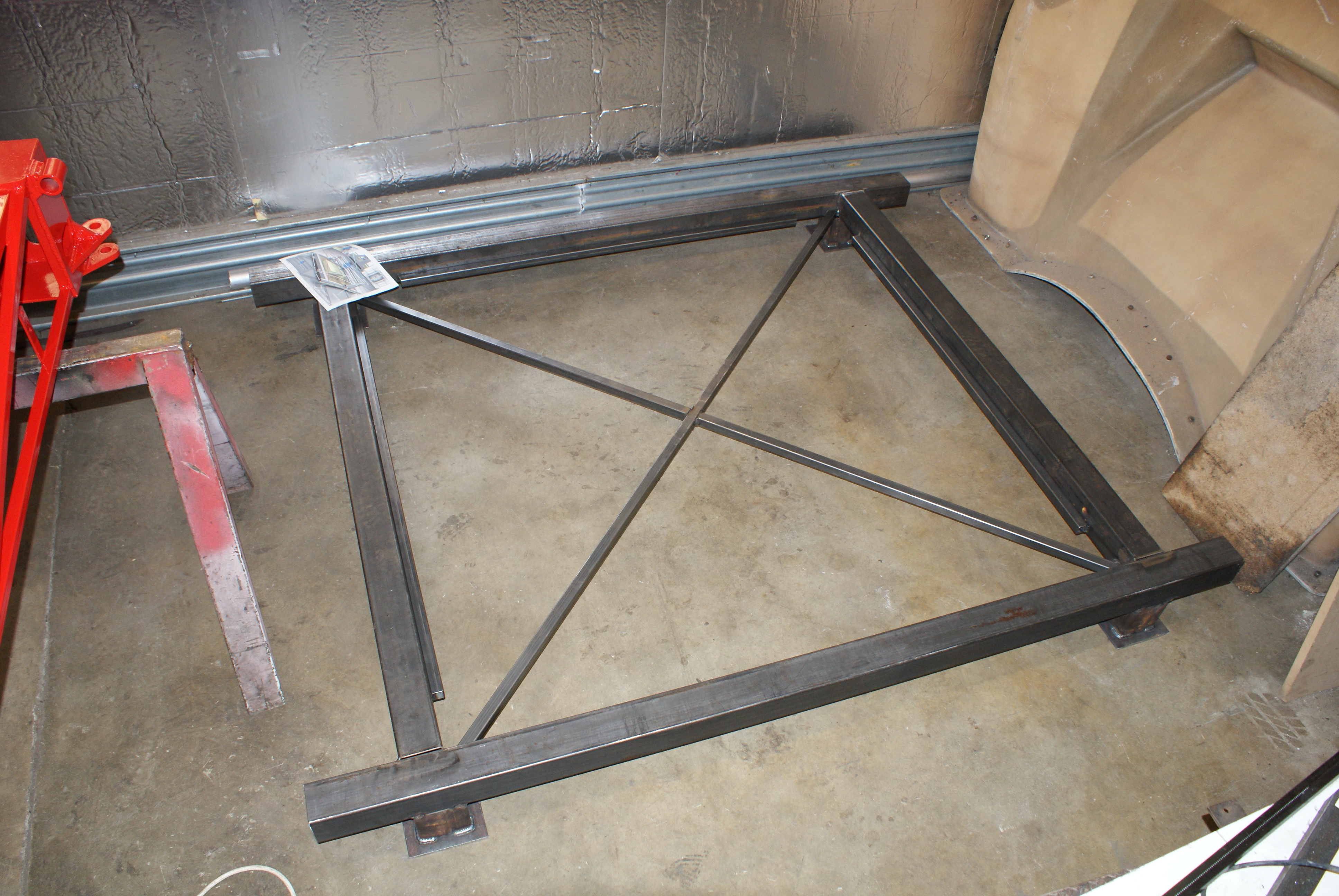
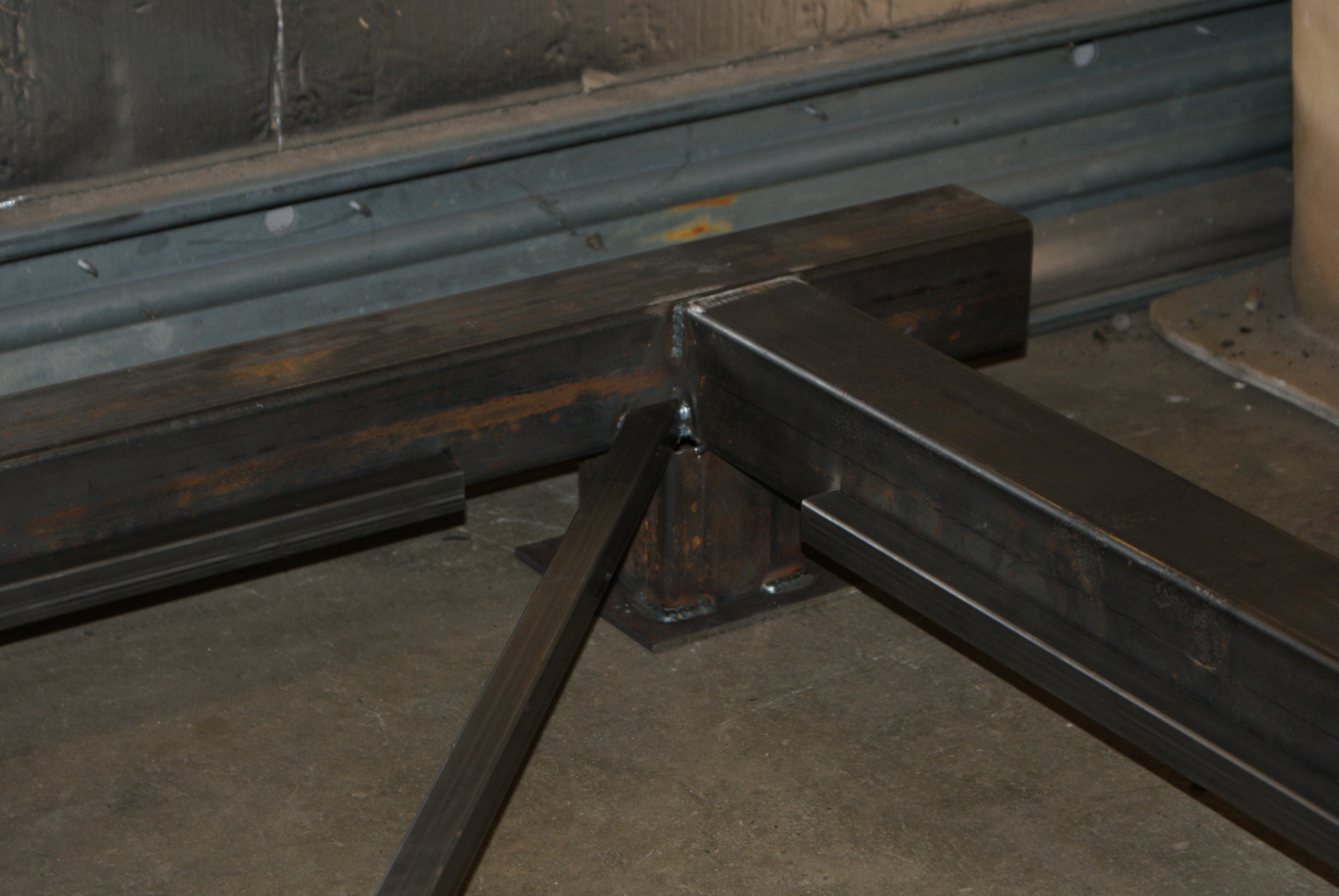
You can just about see the plan on the far left leg!
I decided that the first thing to make was the Z-axis, since this would give the separation for the Y-axis, and also it's the most complex part.
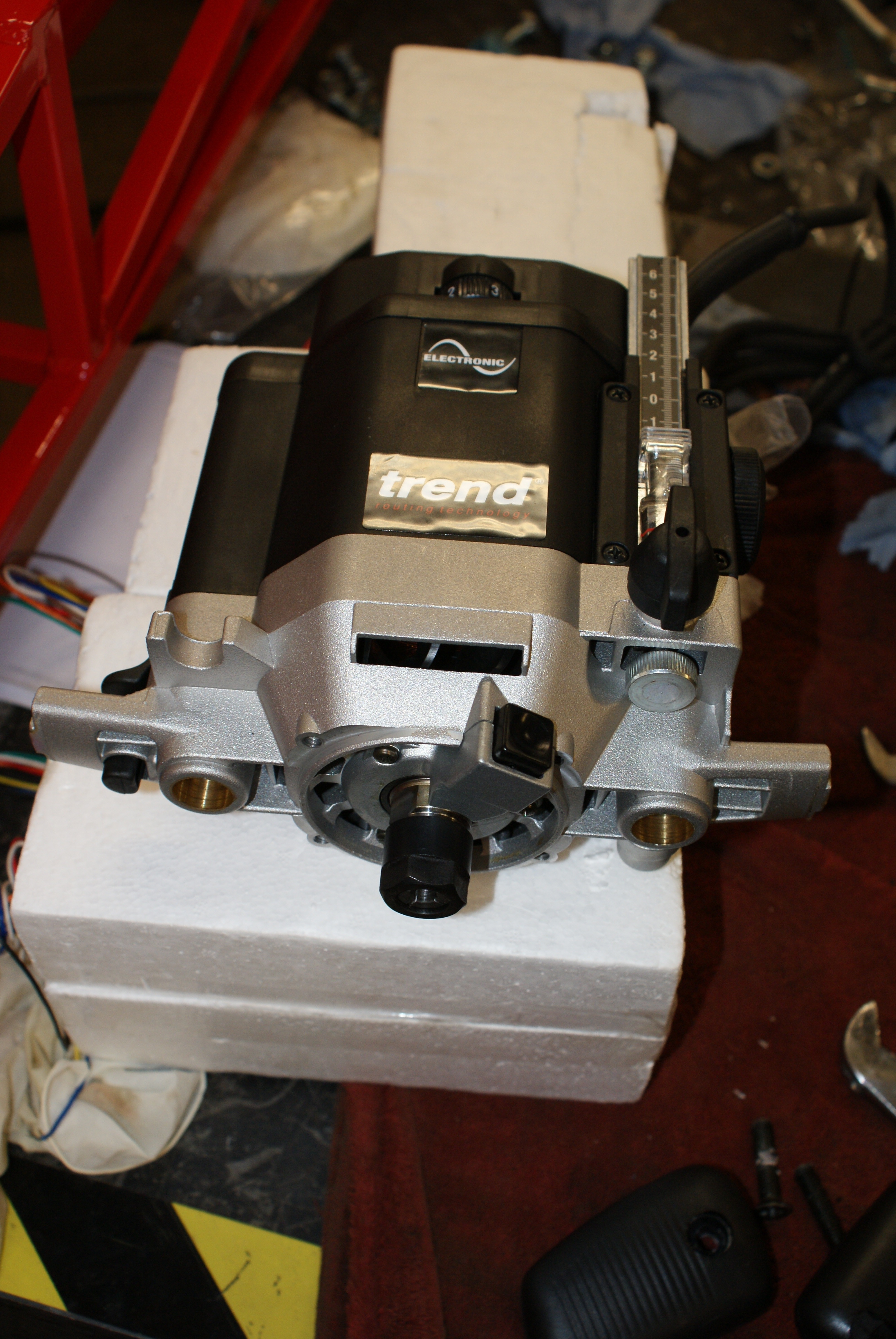
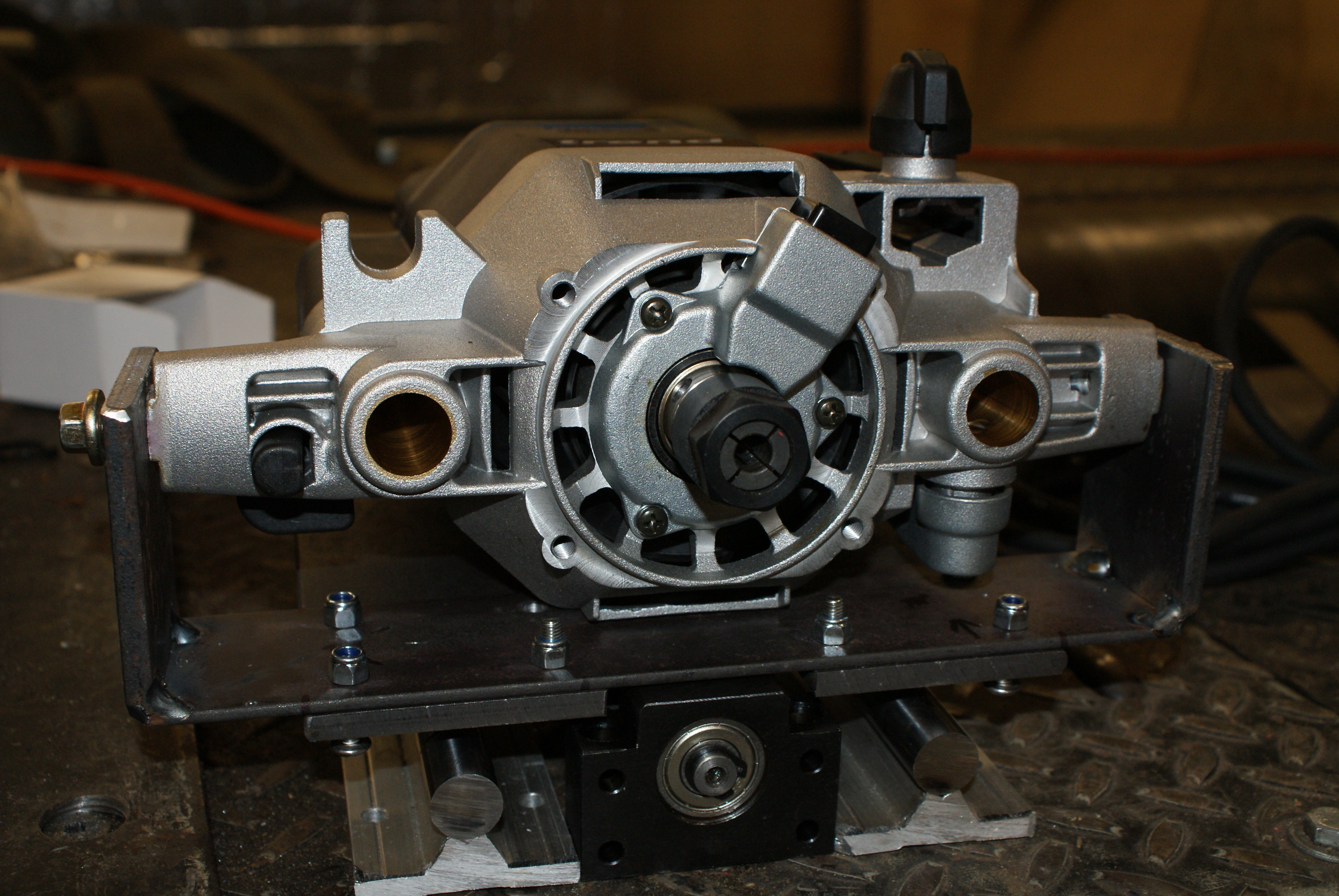
To do that, I needed to strip the router - this is the Trend T10 router:
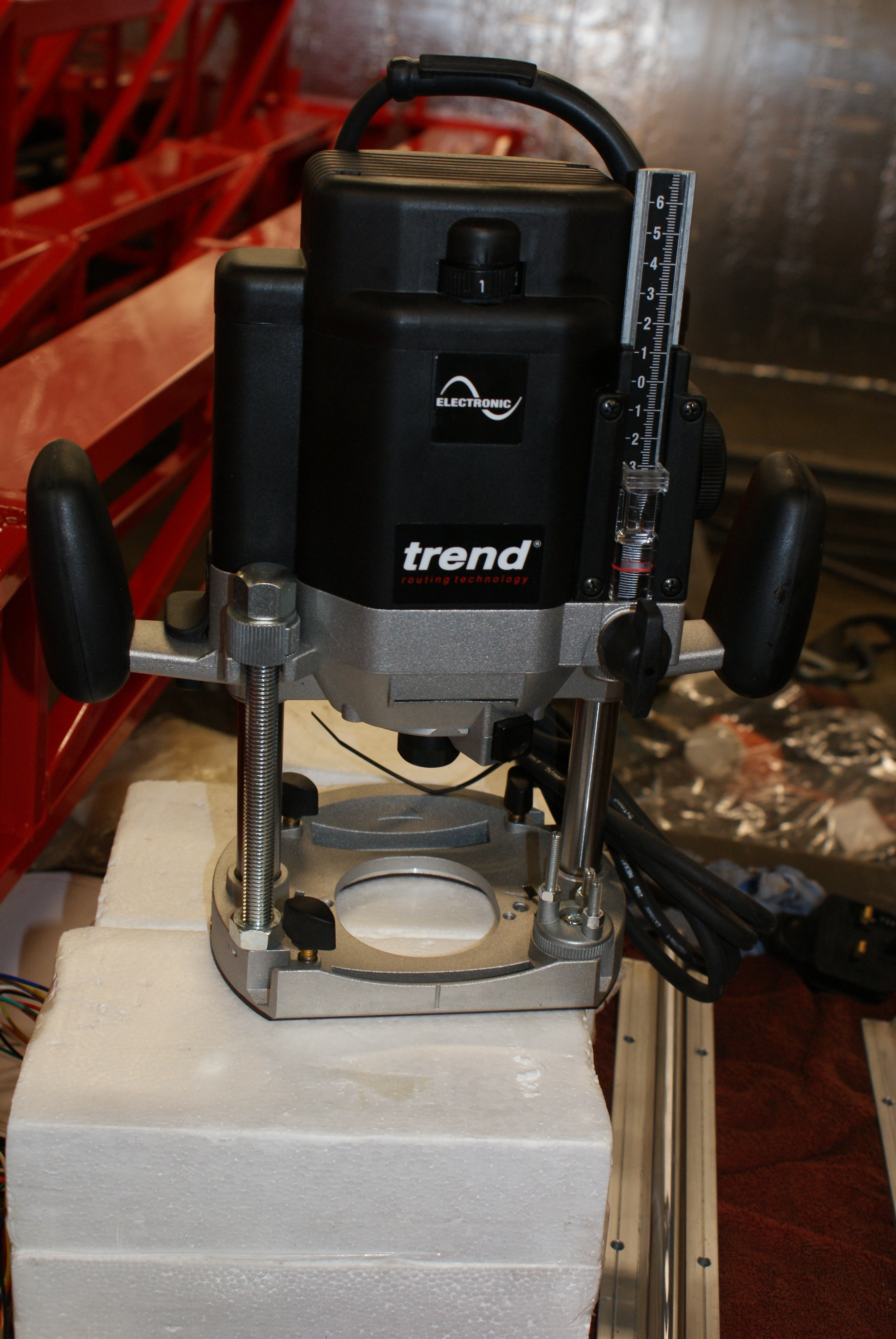
Removing the limit screw (front left as you look at it) allowed the base to be removed:
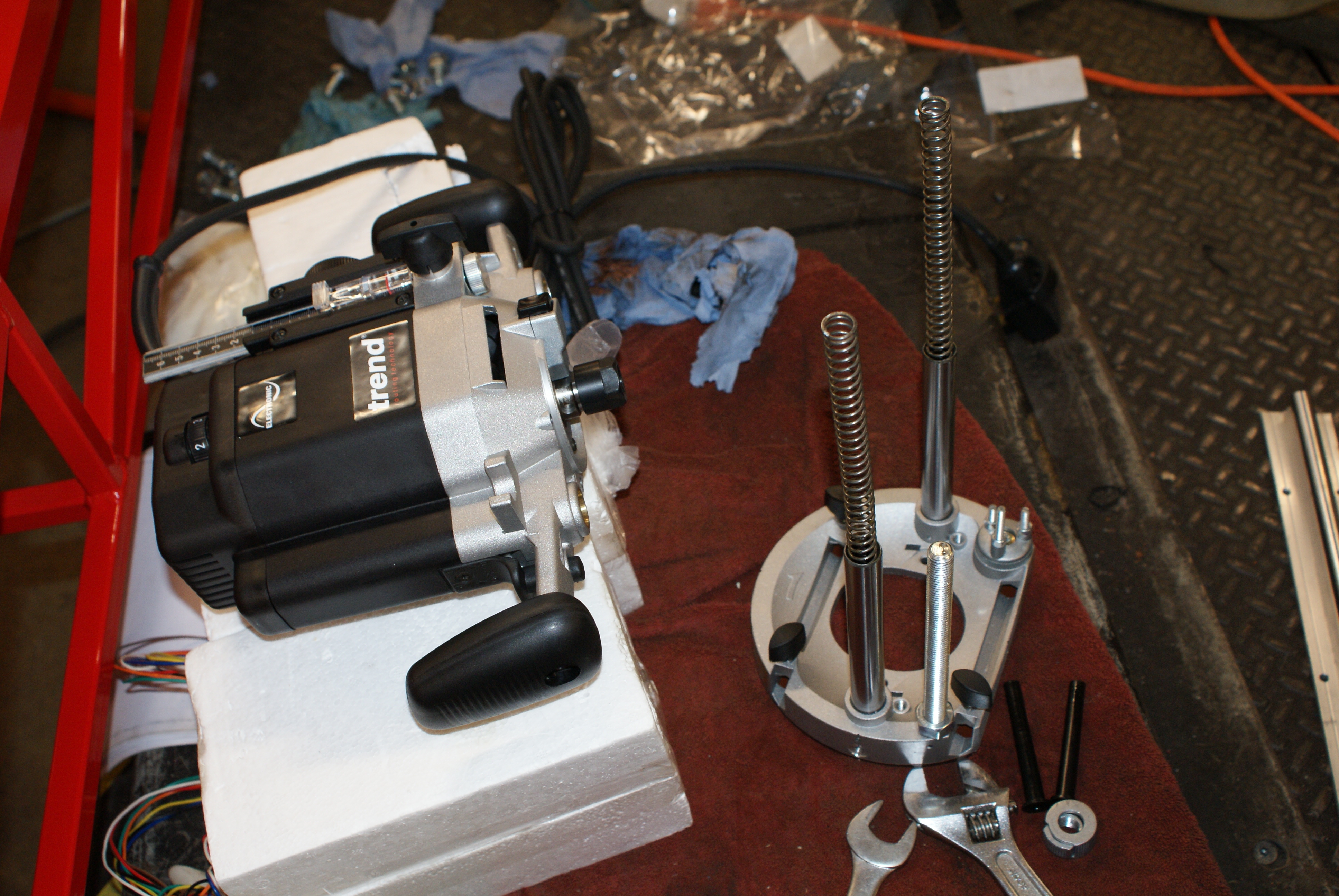
And then the handles were removed:
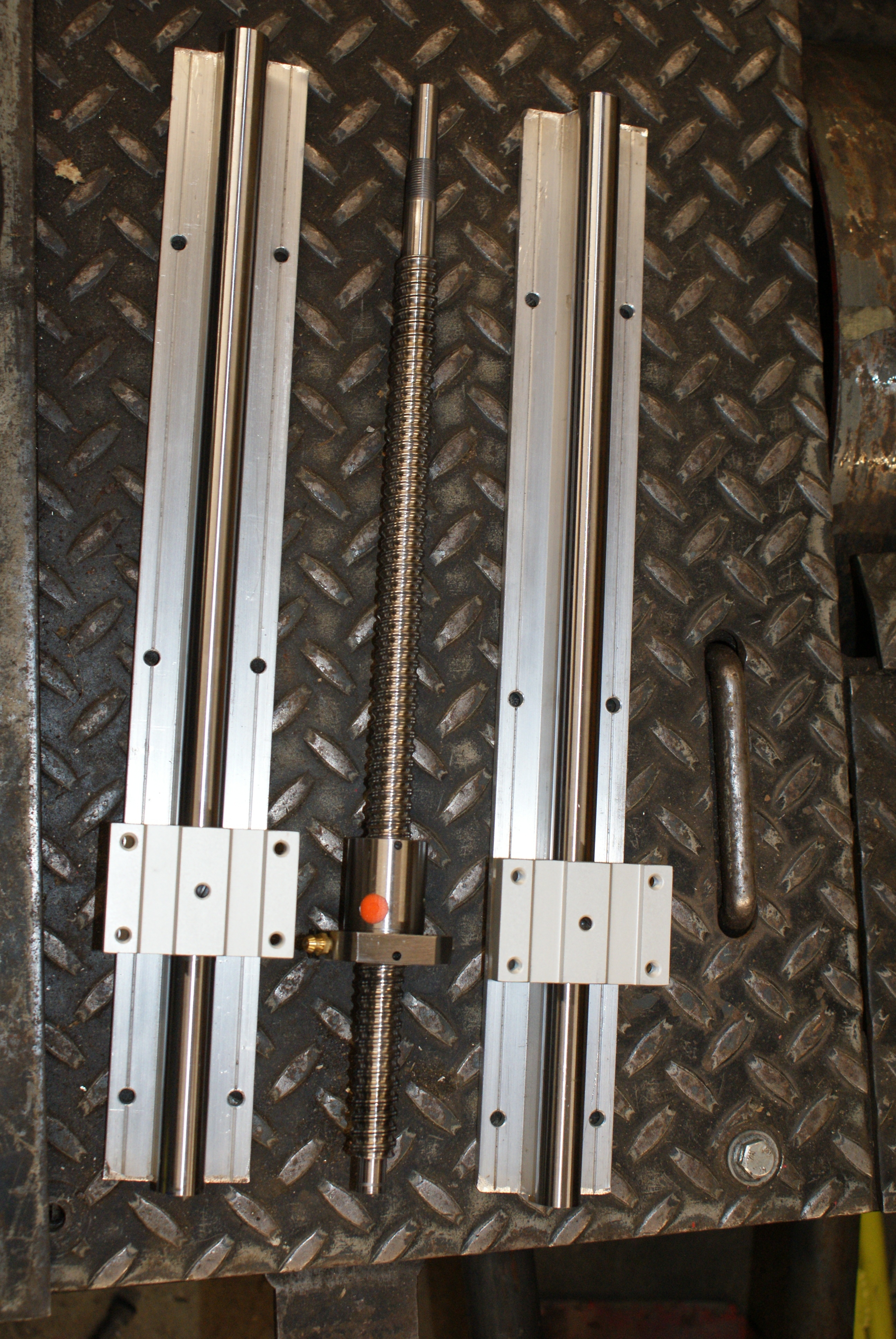
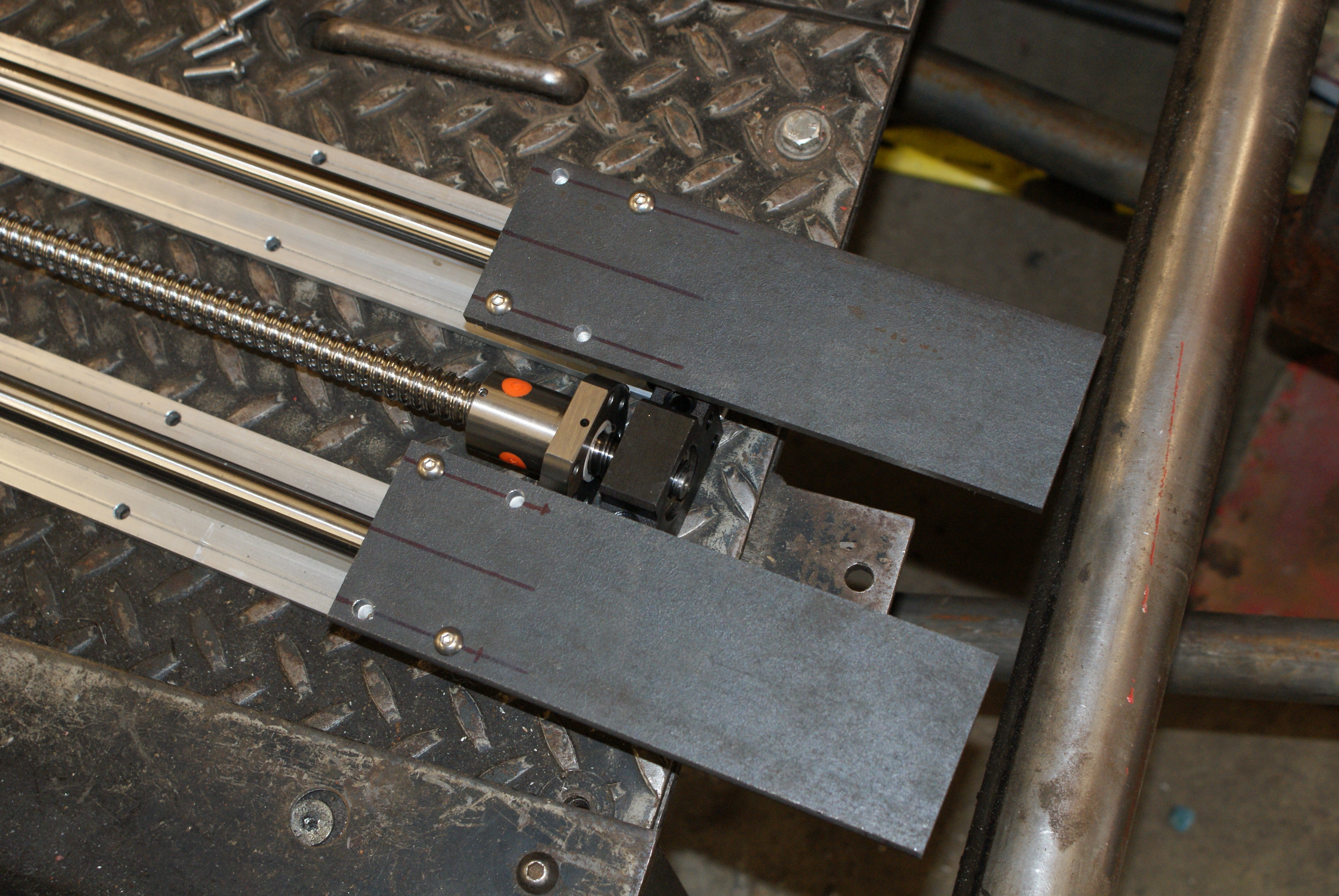
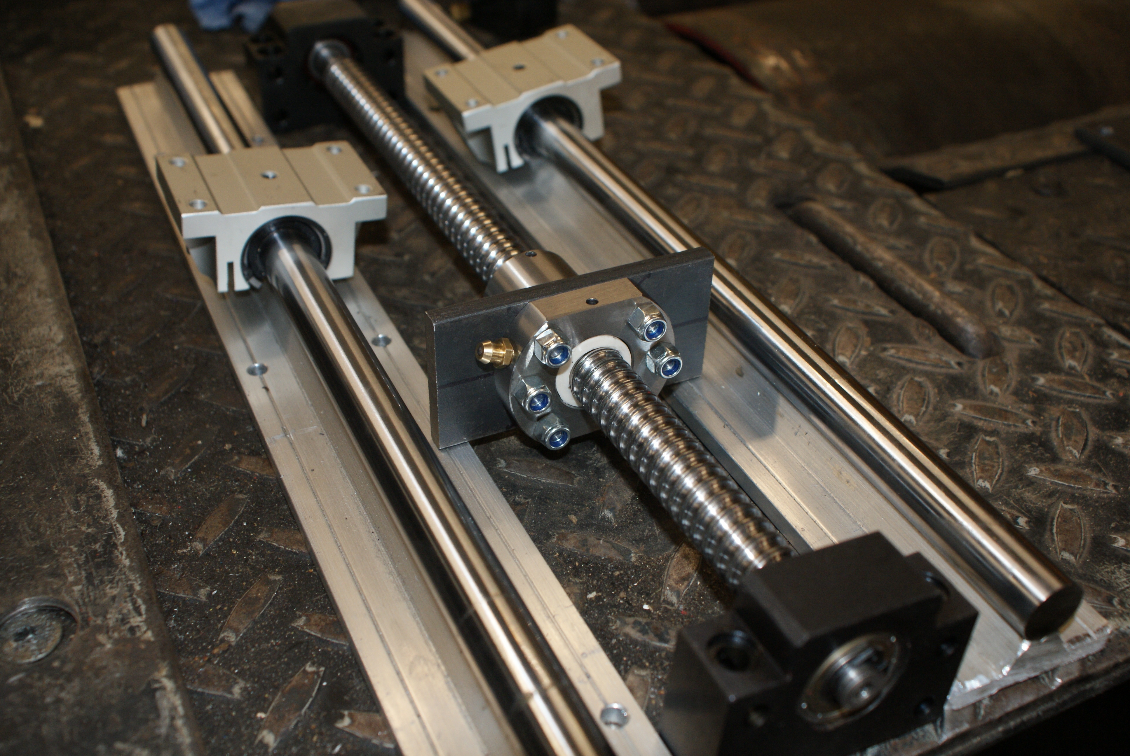
This is the rough layout for the Z-axis - the two 400mm long supported rails either side of the ballscrew (a fairly standard arrangement):
The router would be mounted to those three:
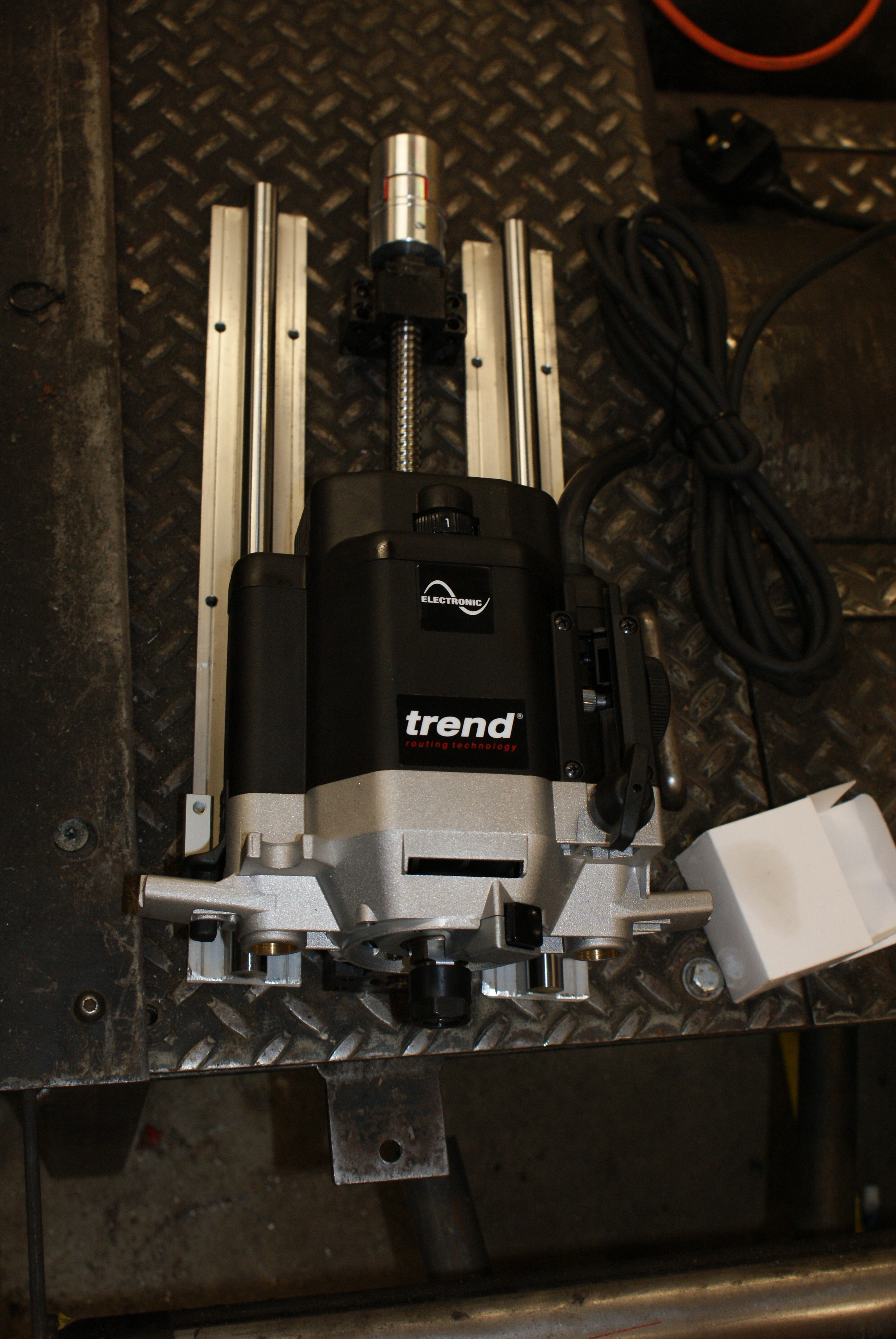
I made some plates and drilled them to take the M5 bolts (Keith's supply is not very good for small bolts - he mainly makes crop sprayers where M16+ are the normal size; I could only find button-head screws in his supply, and no washers).
I decided to mount the router using the handle mounts - there is space underneath for a circular mount, but the locking mechanism for the shaft would need to be cut out, and it's not a nice angle, nor shape.
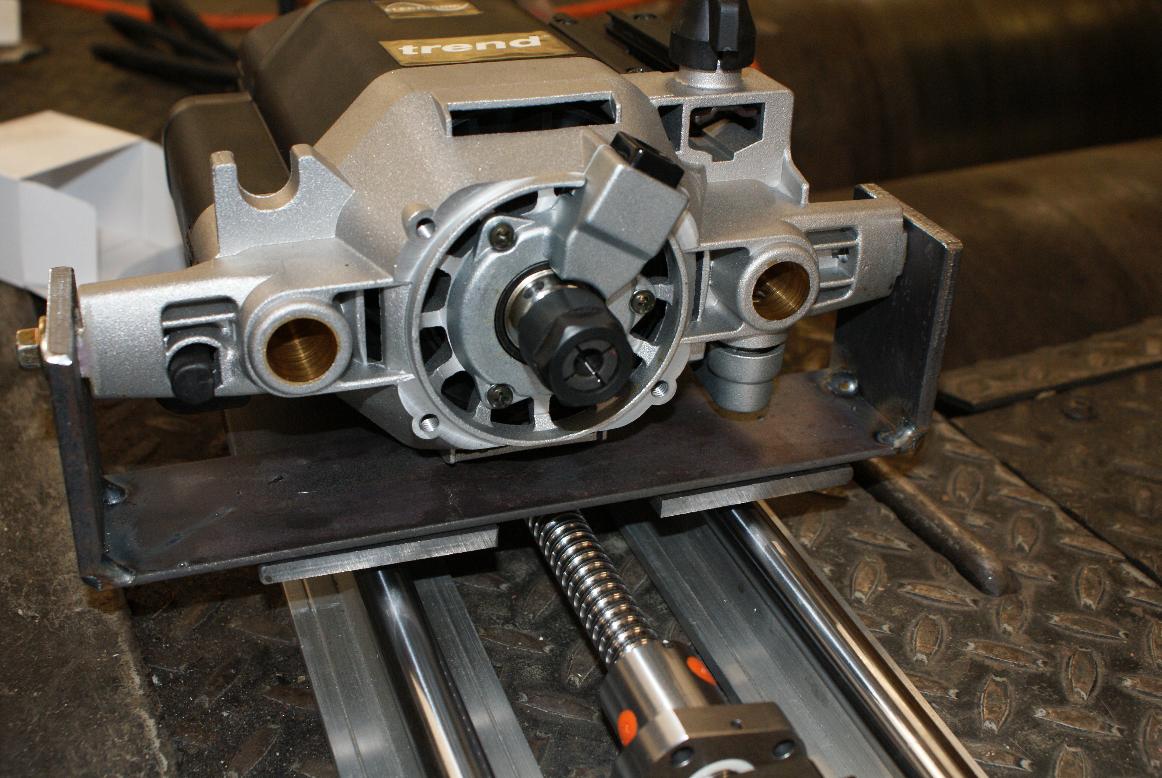
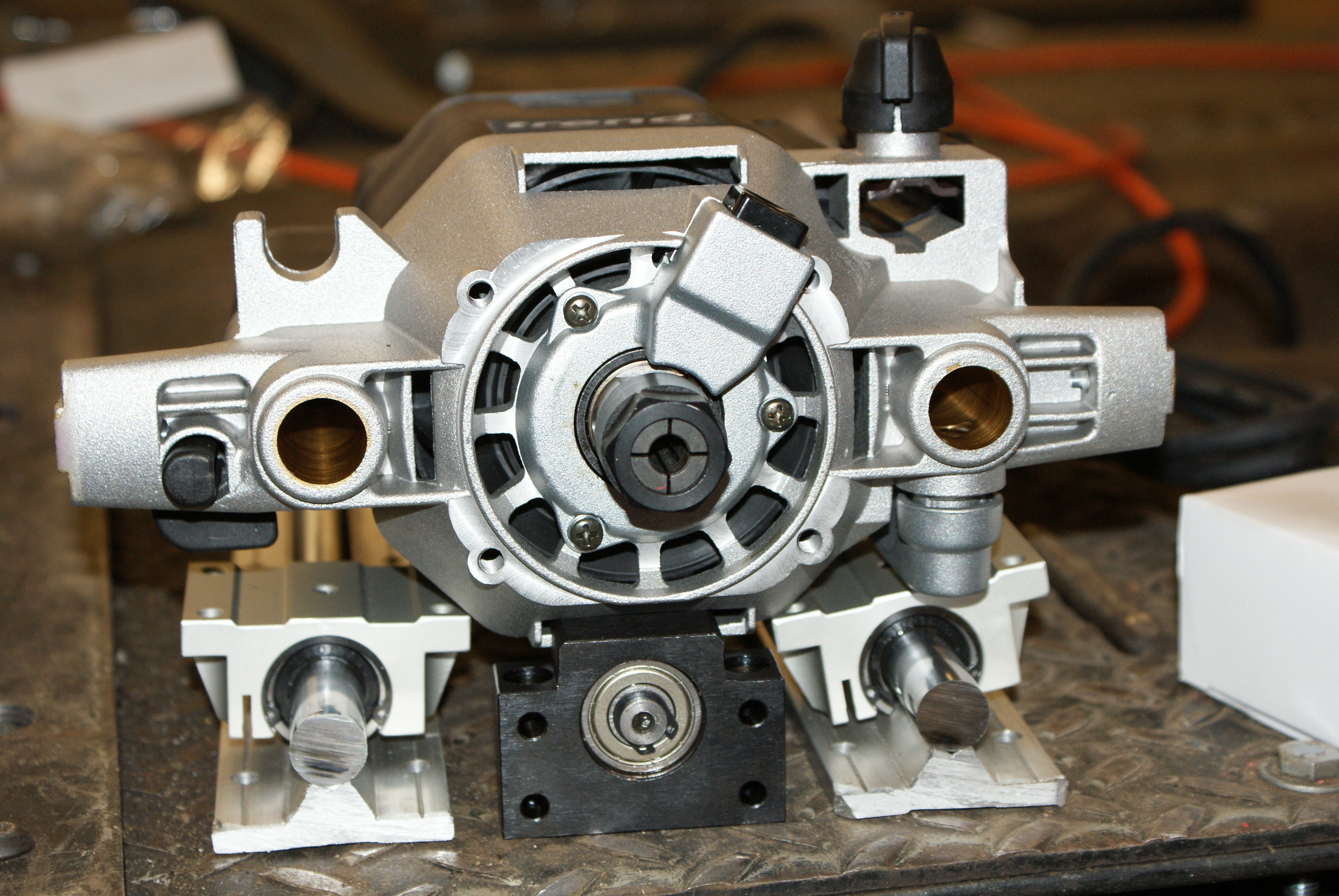
This is then bolted it to the two plates off the shaft blocks (note that only two bolts have been tightened in this shot):
The ballscrew nut would need to be attached to this as well, so I made a mounting plate for it.
There was then a bit of an accident in the workshop (not my doing!). While cutting some steel plate, one of the guys accidentally dropped a plate onto the power feed for the machine he was using - straight through the 3-phase power cable. This only caused the fuse to go, but it meant that it was out of action, and I found the drill was no longer working (although after packing up, I found out that it had only been turned off because they thought it wasn't being used).
So that was the end of day 1 - I would've liked to have got the Z-axis ballscrew attached to the router mechanism, but that shouldn't take very long tomorrow. I hope to finish off the Z-axis tomorrow, and the day after then start on the Y-axis (which should be easier, but it is larger).