Assembly part 1
The parts started arriving - it was quite exciting!
Stepper motors
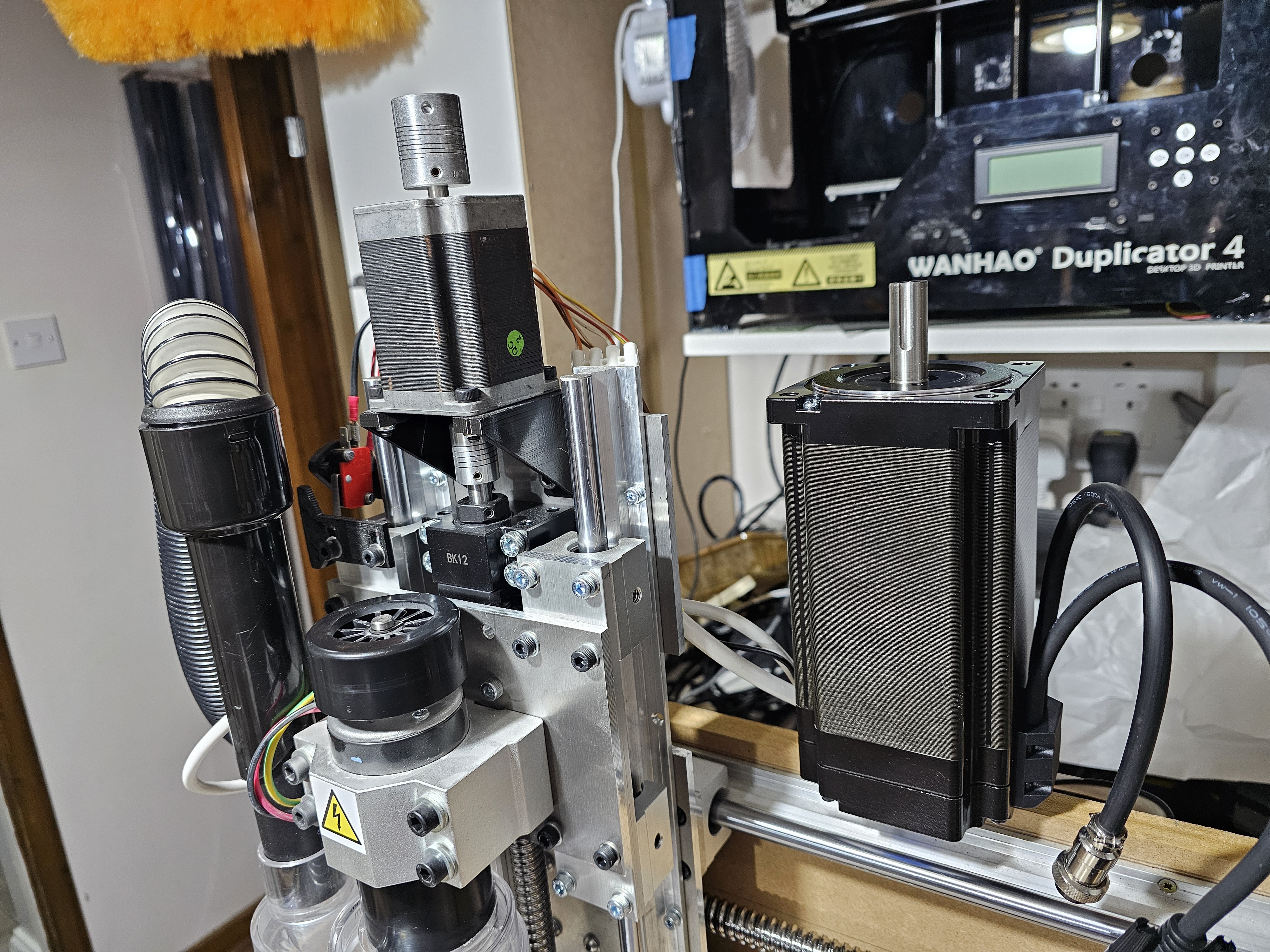
The stepper motors were definitely in a different league to the ones I had used in V4:
Aluminium
The aluminium arrived in one go:
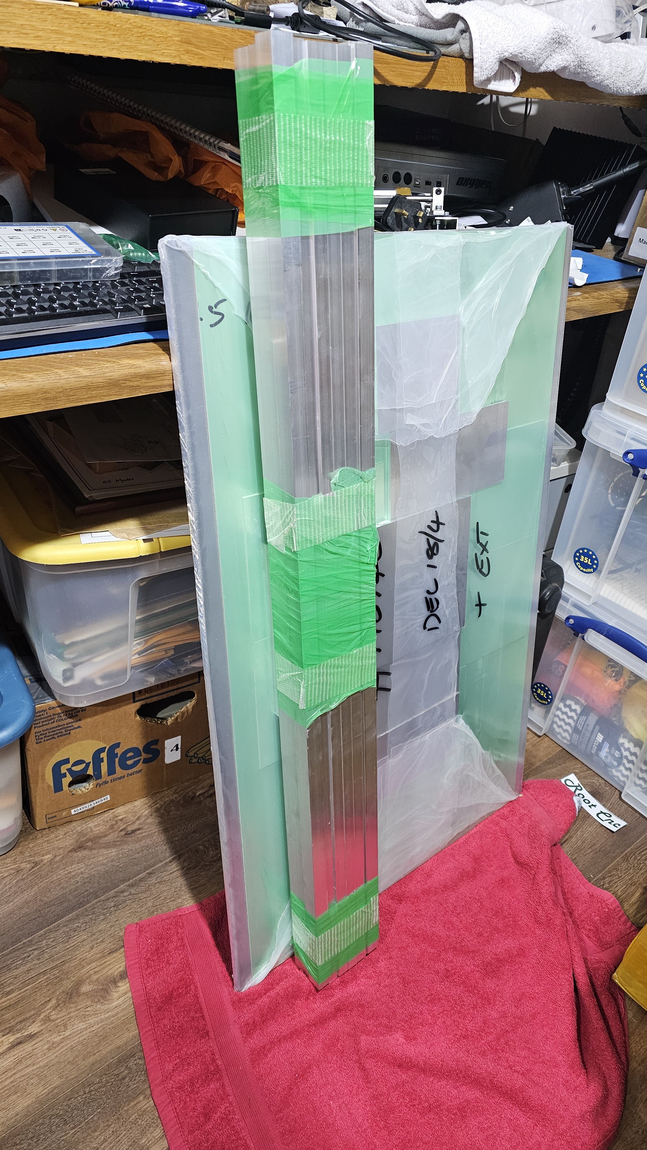
And the base, which was 10mm sheet, fitted nicely on the trolley:
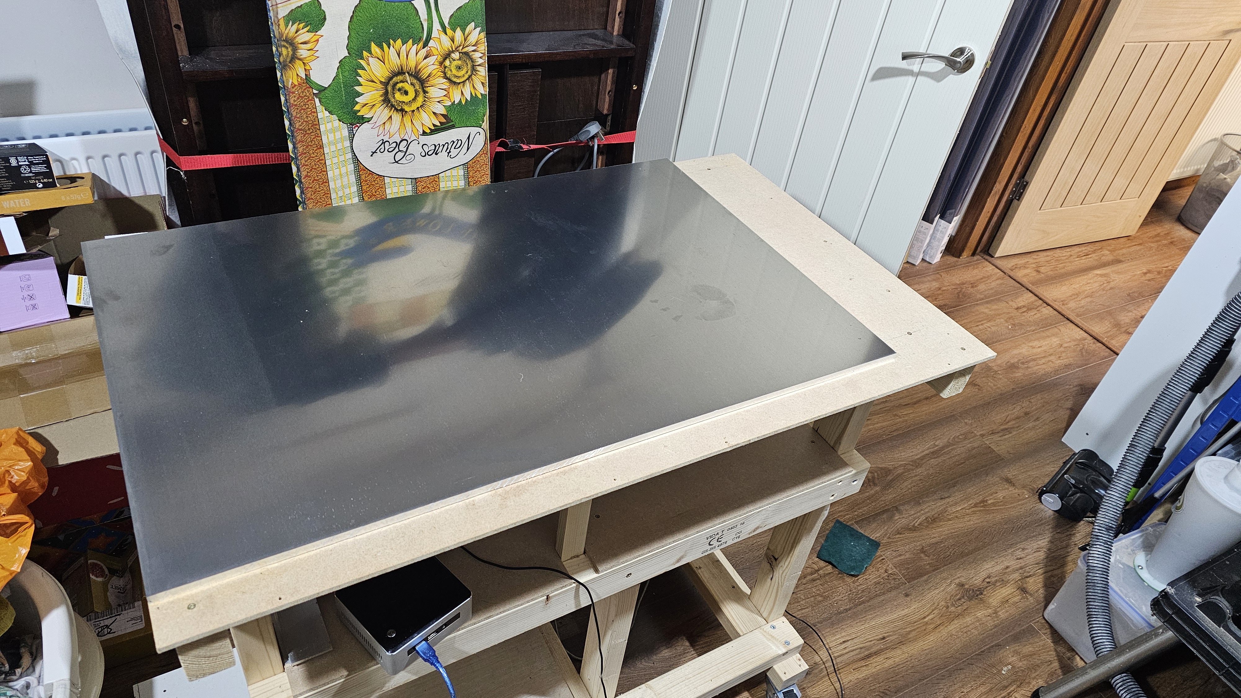
Cutting pieces
The aluminium bar needed to be cut to pieces. Using the CAD model, I worked out the lengths of everything I needed, and then used the chop saw to cut them out:
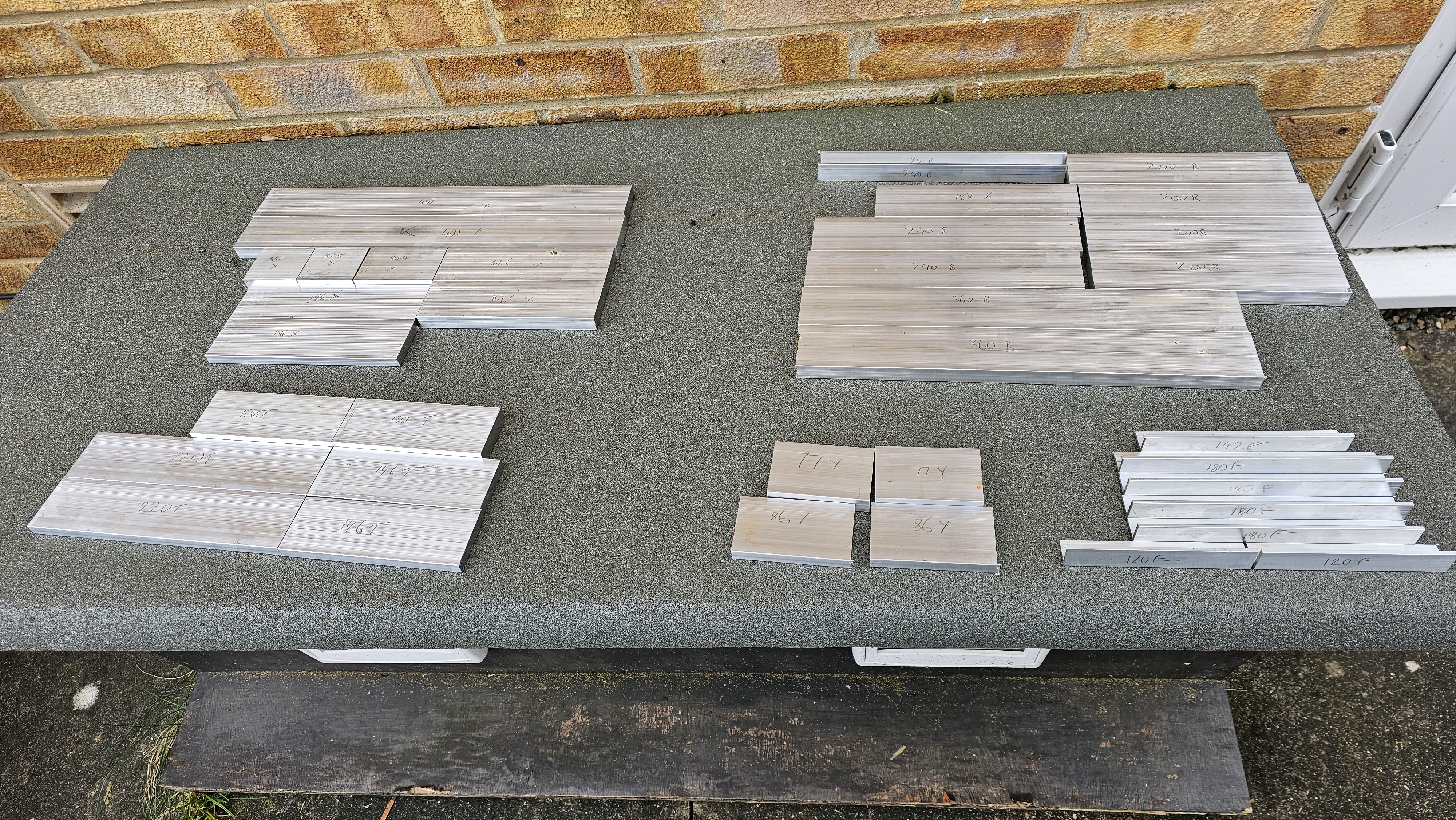
Each part was labelled with their length, and their position:
- T = Tower
- X = X-axis
- Y = Y-axis
- F = Fixing
- B = Bed
Machining
CNC V4 did the machining, drilling the basic hole positions (finished with a pillar drill), and machining pockets for bolts. For example, the left-hand side and bearing support for the Z-axis:
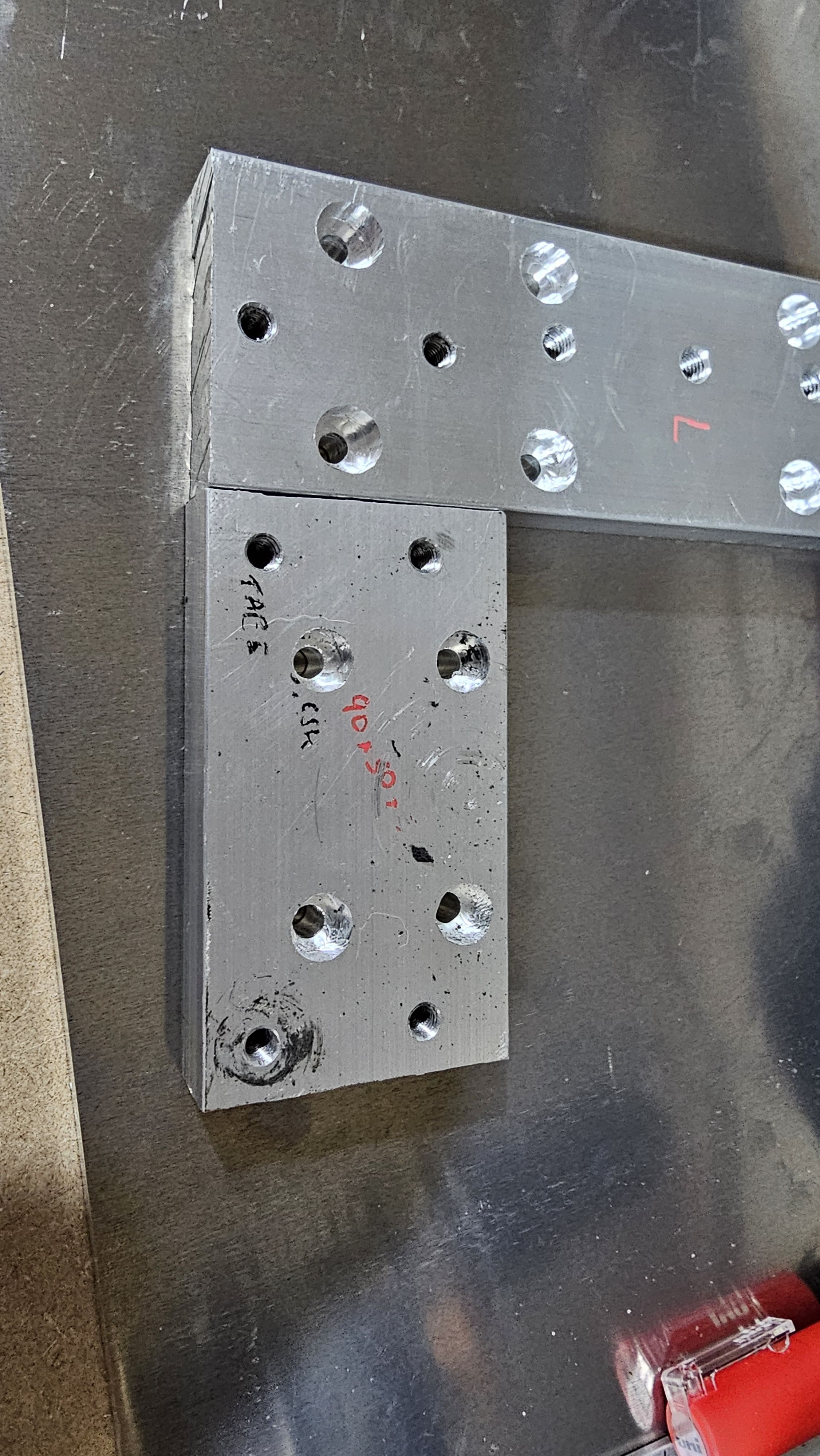
Tower supports
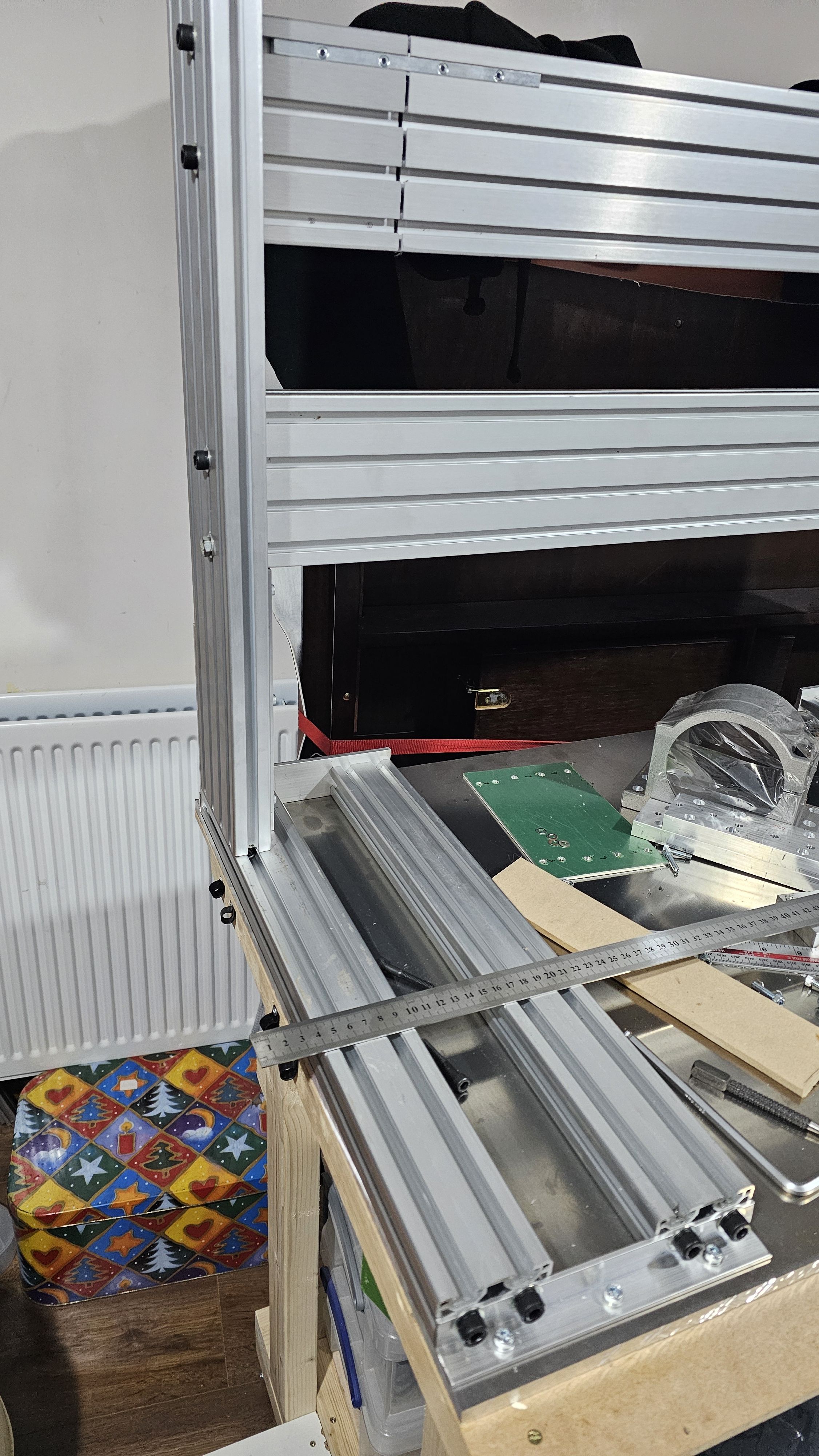
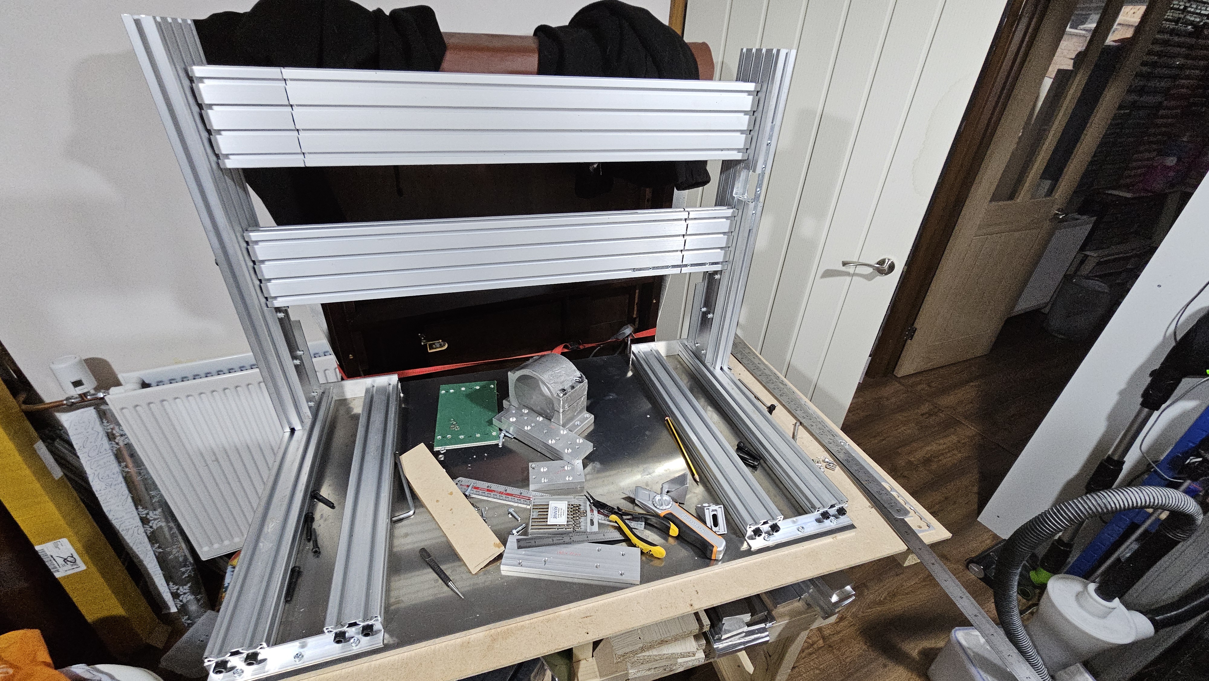
The first parts to be initially assembled were the tower base supports. These were made from two 3060 channel sections each side, one to support the vertical towers, the other to hold the linear rails.
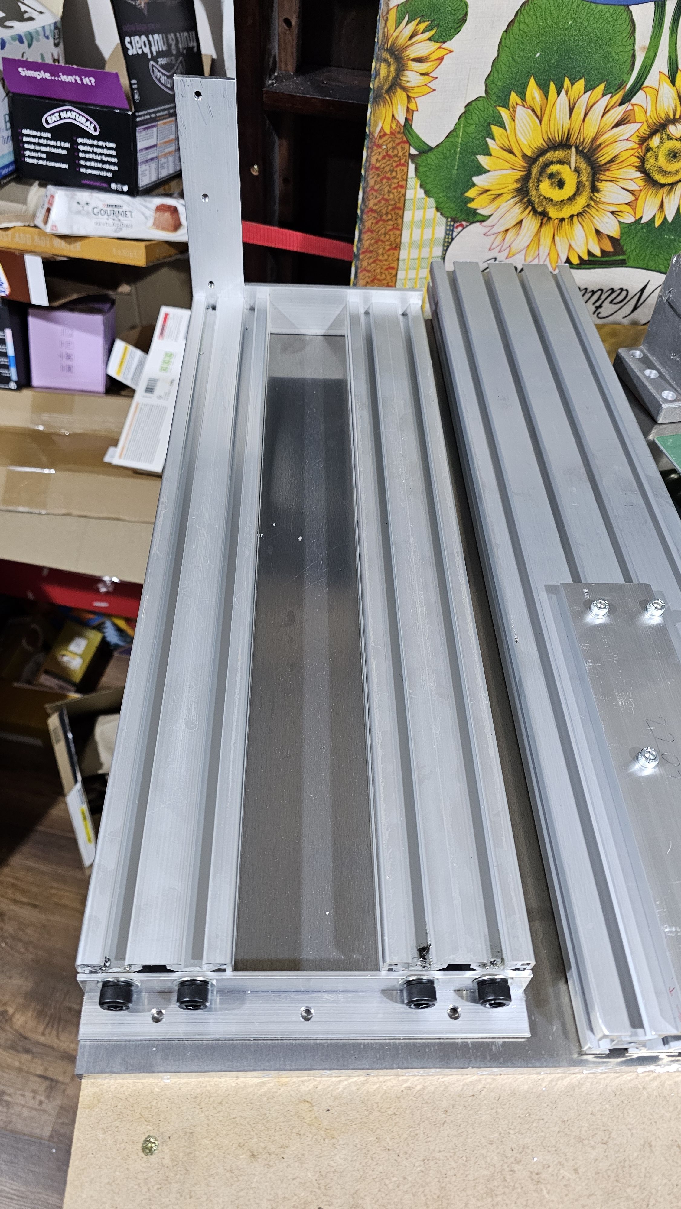
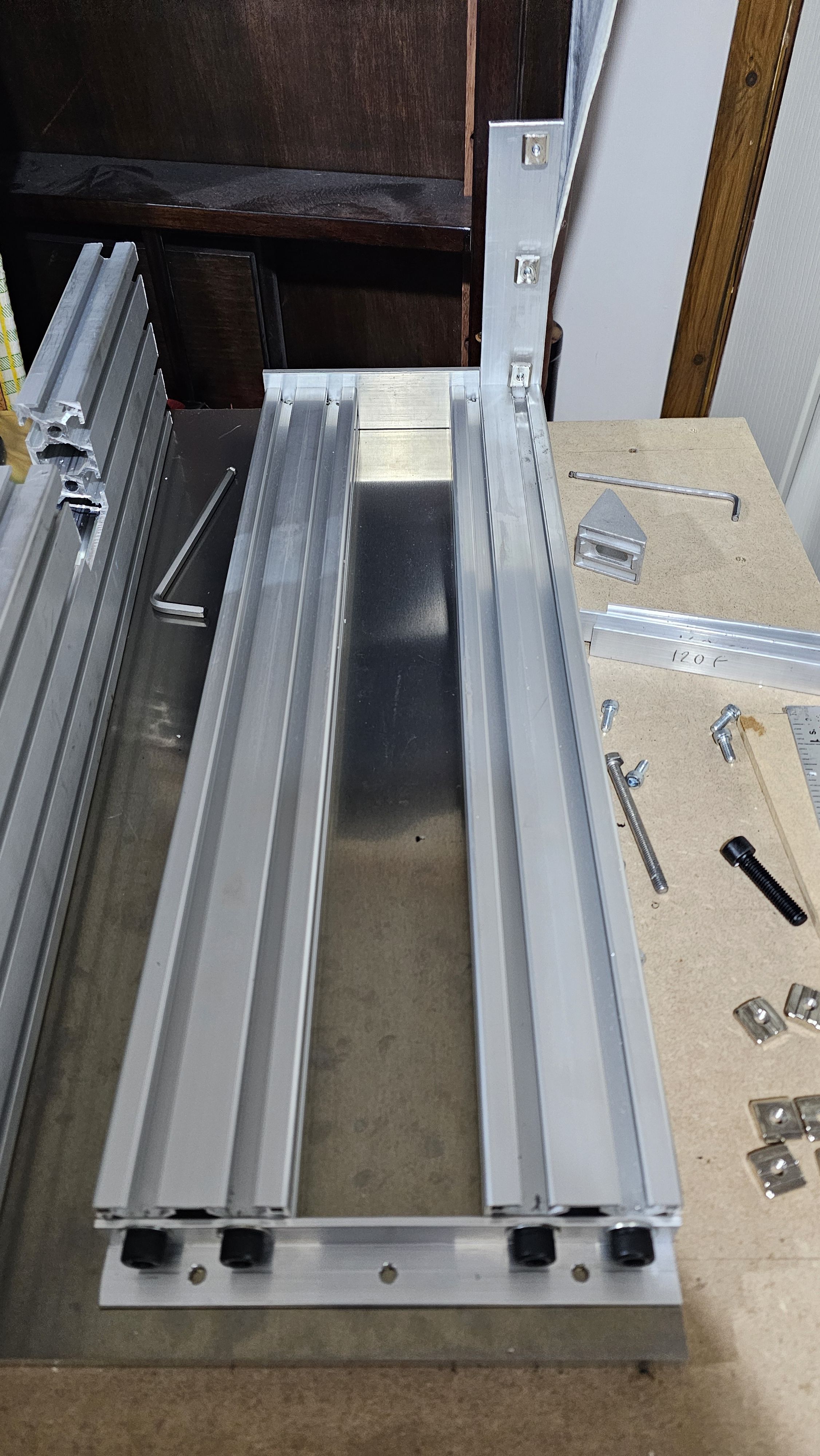
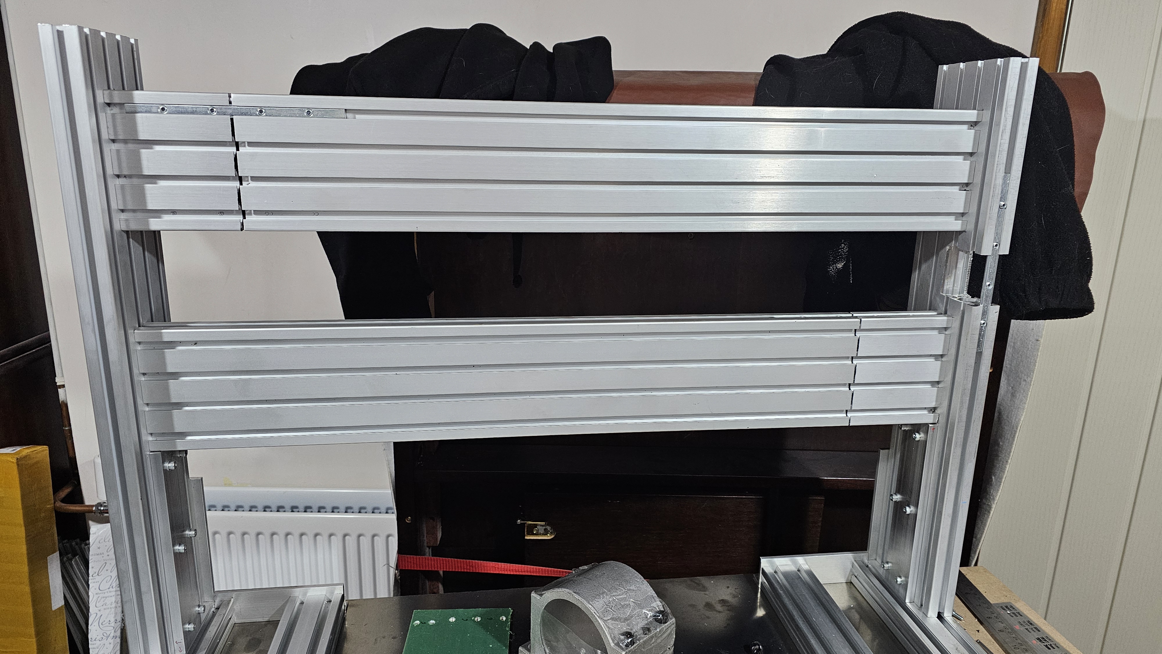
The tower section would look like this when assembled:
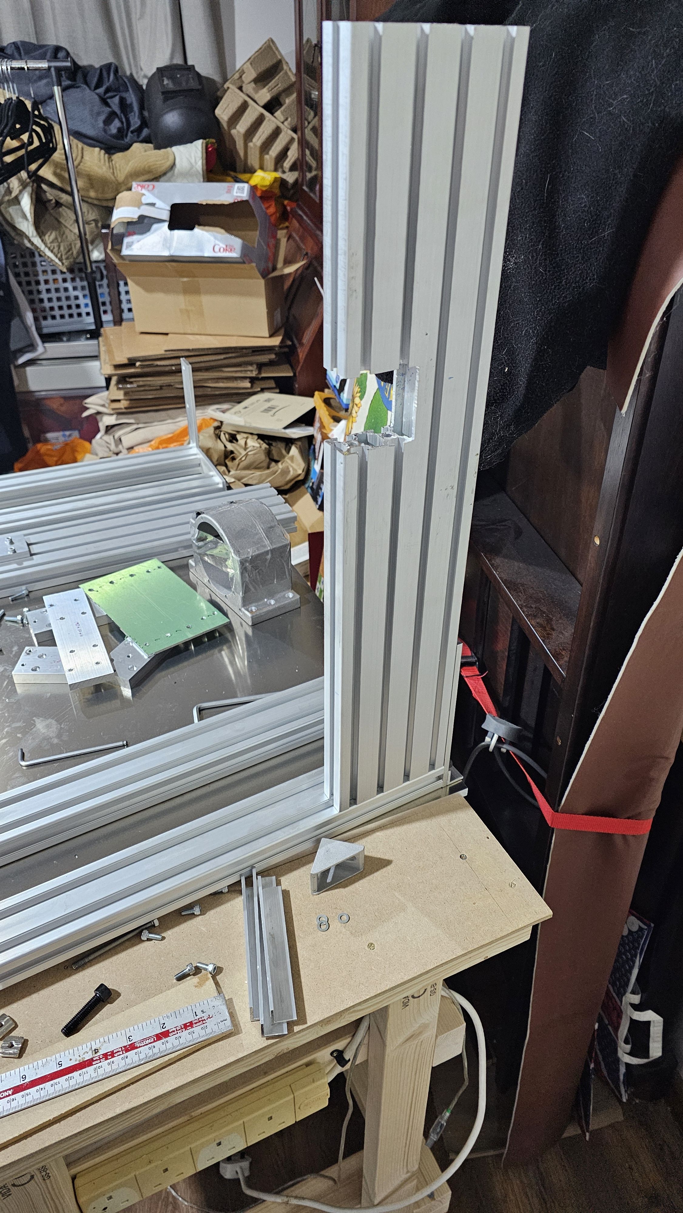
X-axis gantry
The X-axis gantry needed to be extended by 100mm as I'd miss remembered the length of the 30120 section (I thought it was 800mm, but it was 700mm instead). It would look like this:
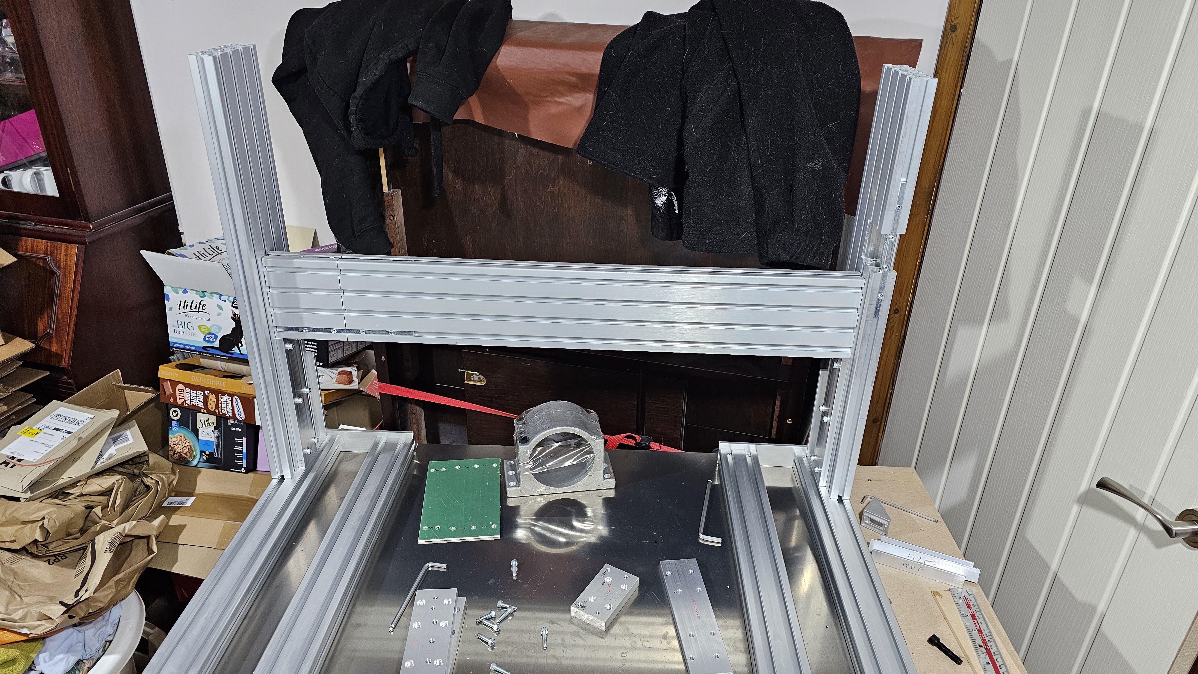
The tower sections have two plates which are the same height - this gives the gantry extra support, as well as helping keep everything square.
Pockets were machined into the underside of the 3060 section aluminium - 4 on each side for the four holes in the 30120 section aluminium, each hole was tapped, and 60mm long bolts were used to secure the tower in place.
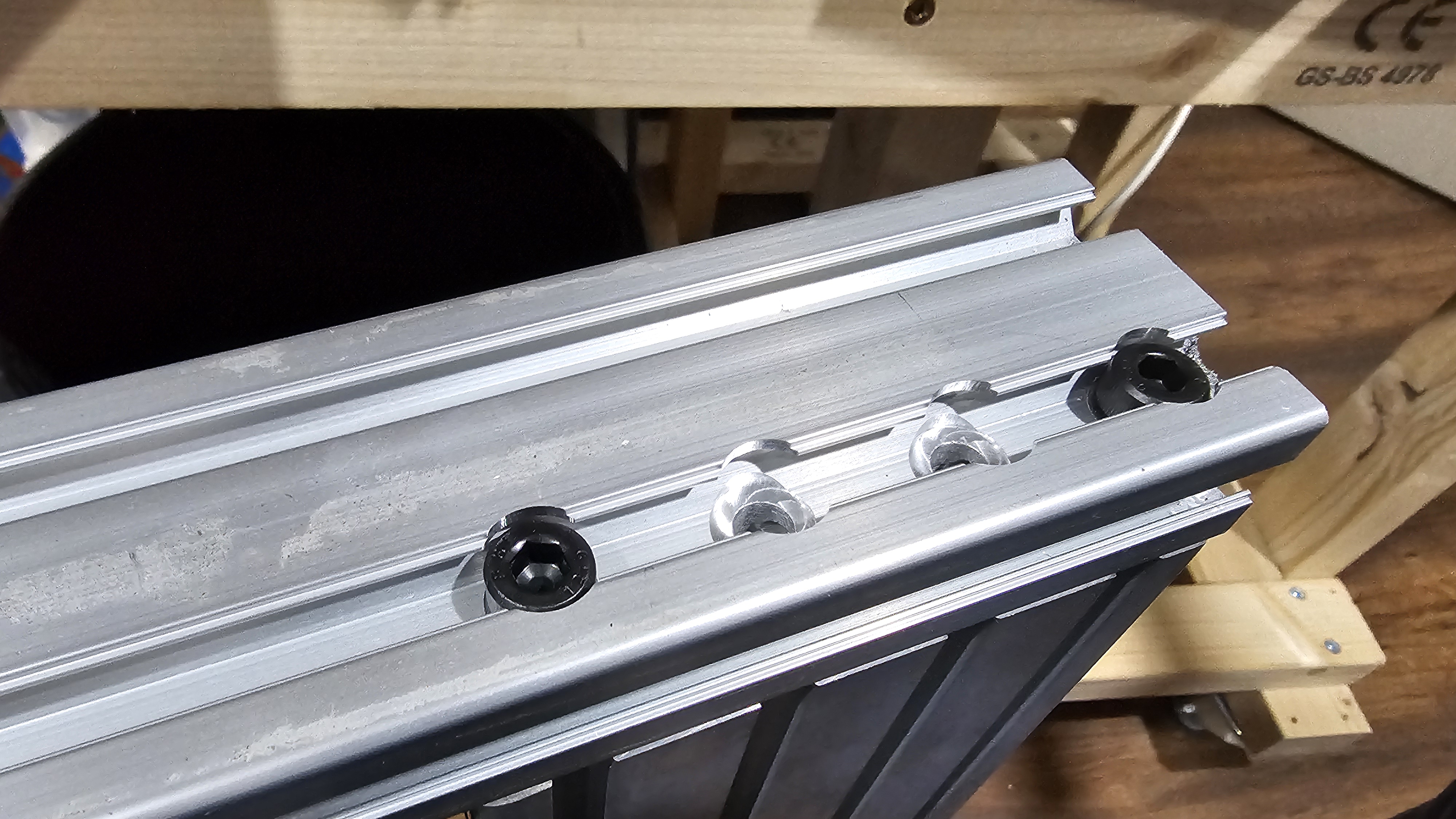
Holes were drilled through the 30120 towers to support the X-axis gantry pieces - although they weren't pocketed. This was before the bolts were tightened:
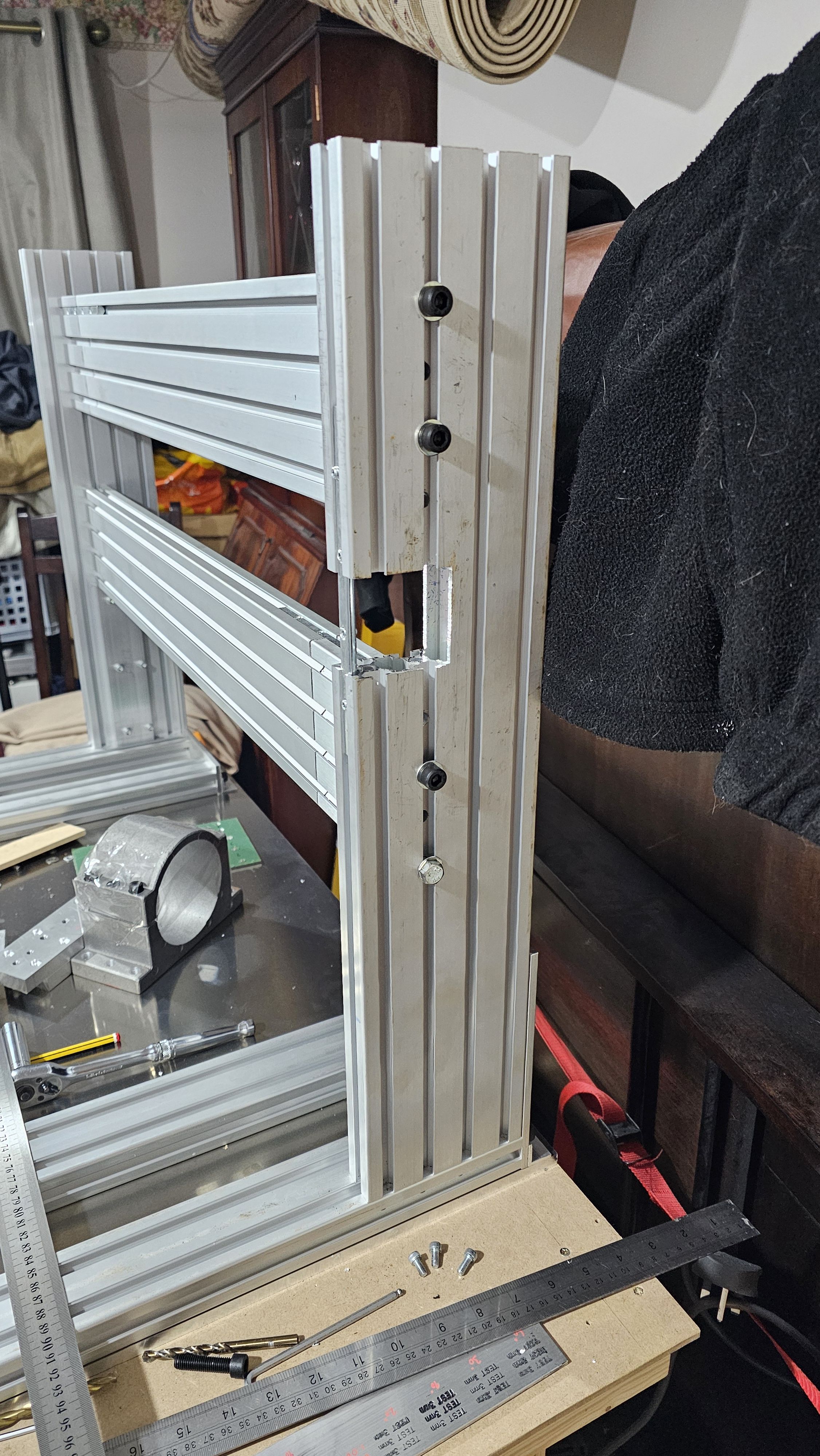
Unfortunately, I'd run out of long enough self-coloured cap bolts, so had to use a hex bolt instead!
With it tightened up: