
Assembly part 3
Z-axis
The Z-axis was the next thing that needed doing.
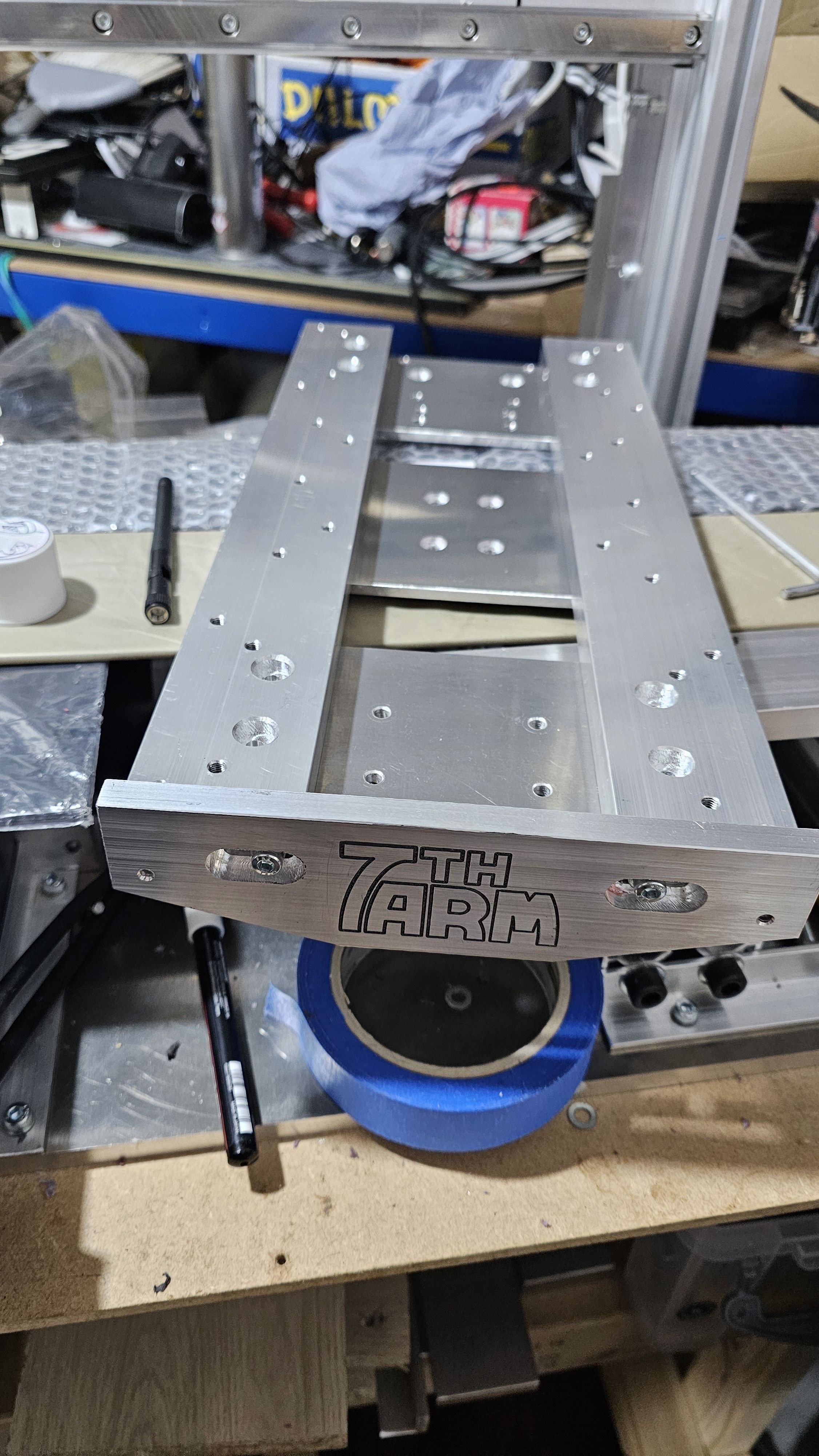
Although I didn't need anything quite so fancy, I made a bottom part of the Z-axis with some ramps (which would trip the limit switches) and stuck a 7th ARM logo on it:
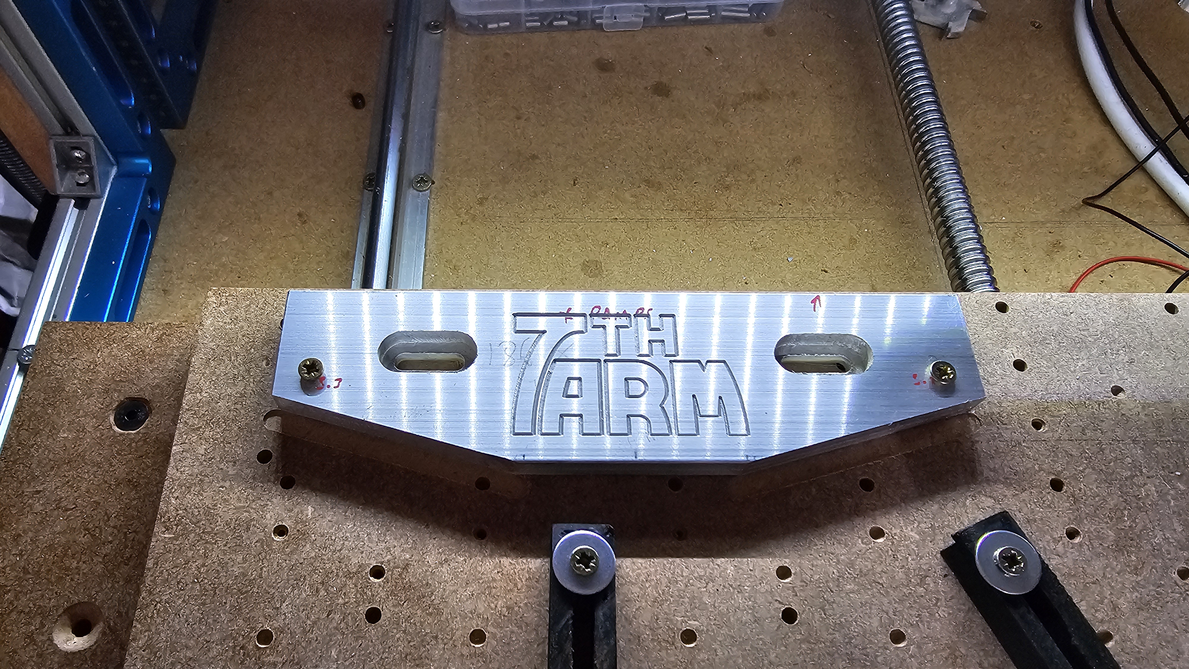
After a lot of machining, it was ready to bolt together:
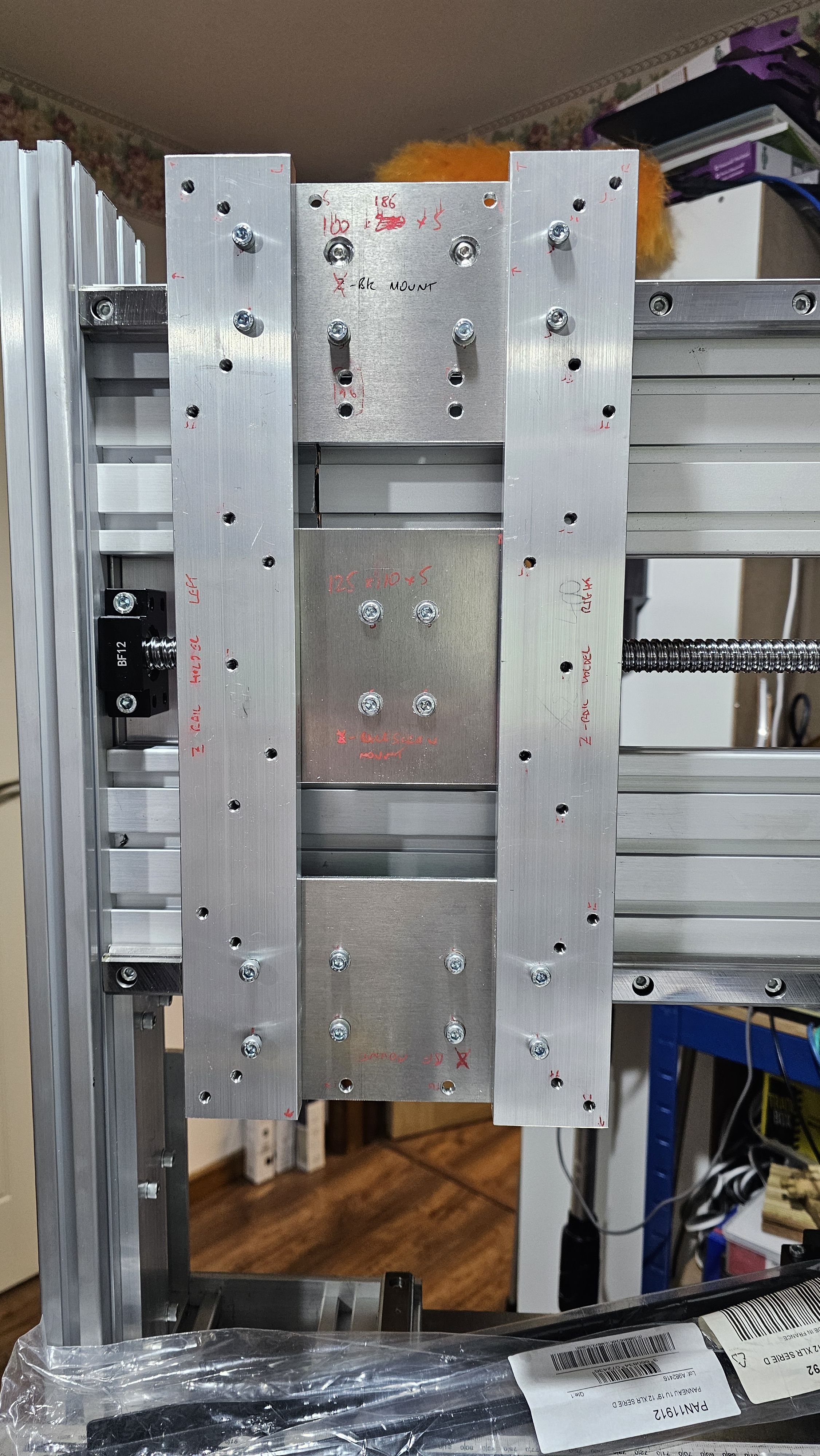
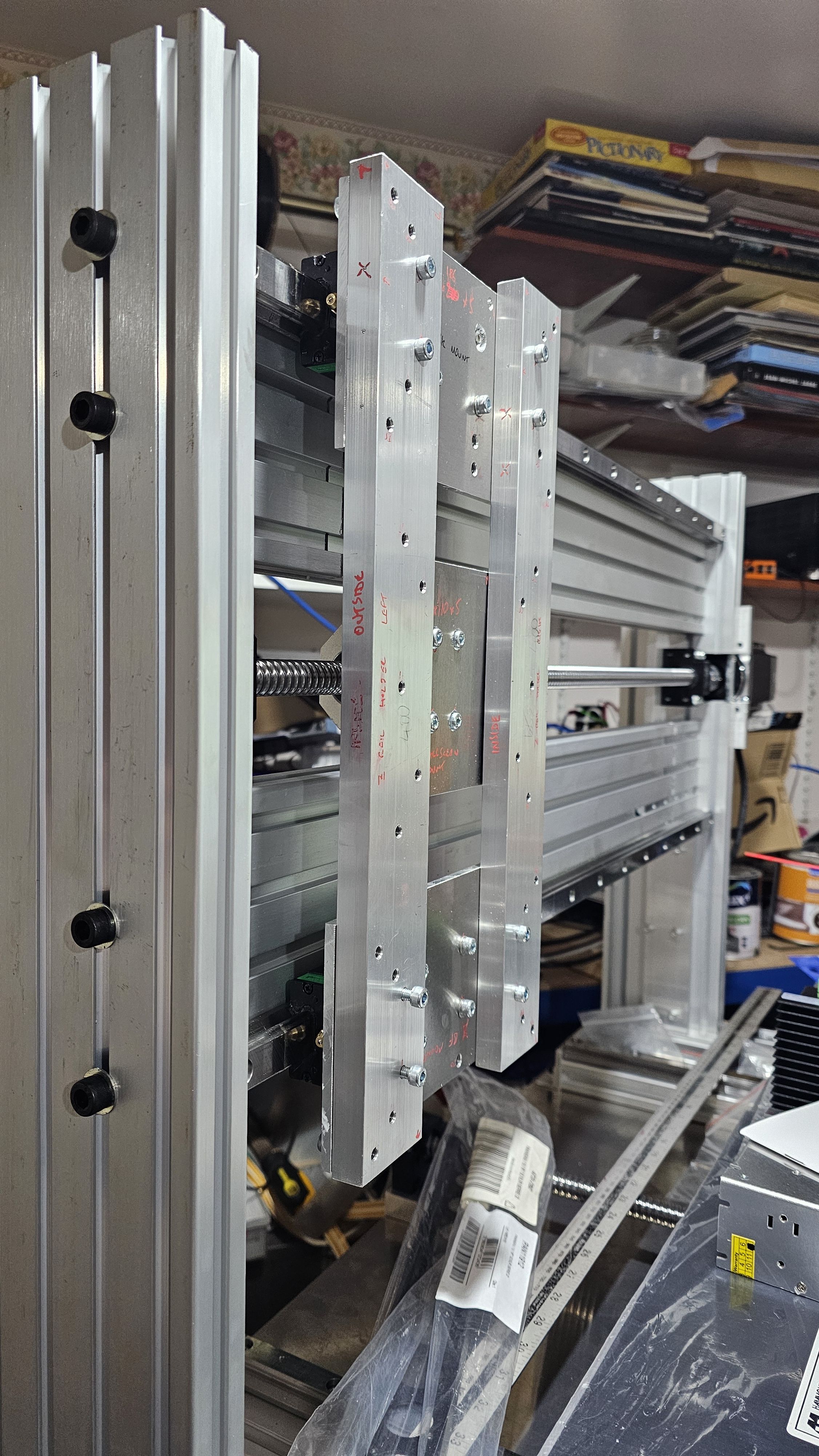
And now the ballscrew could be fitted
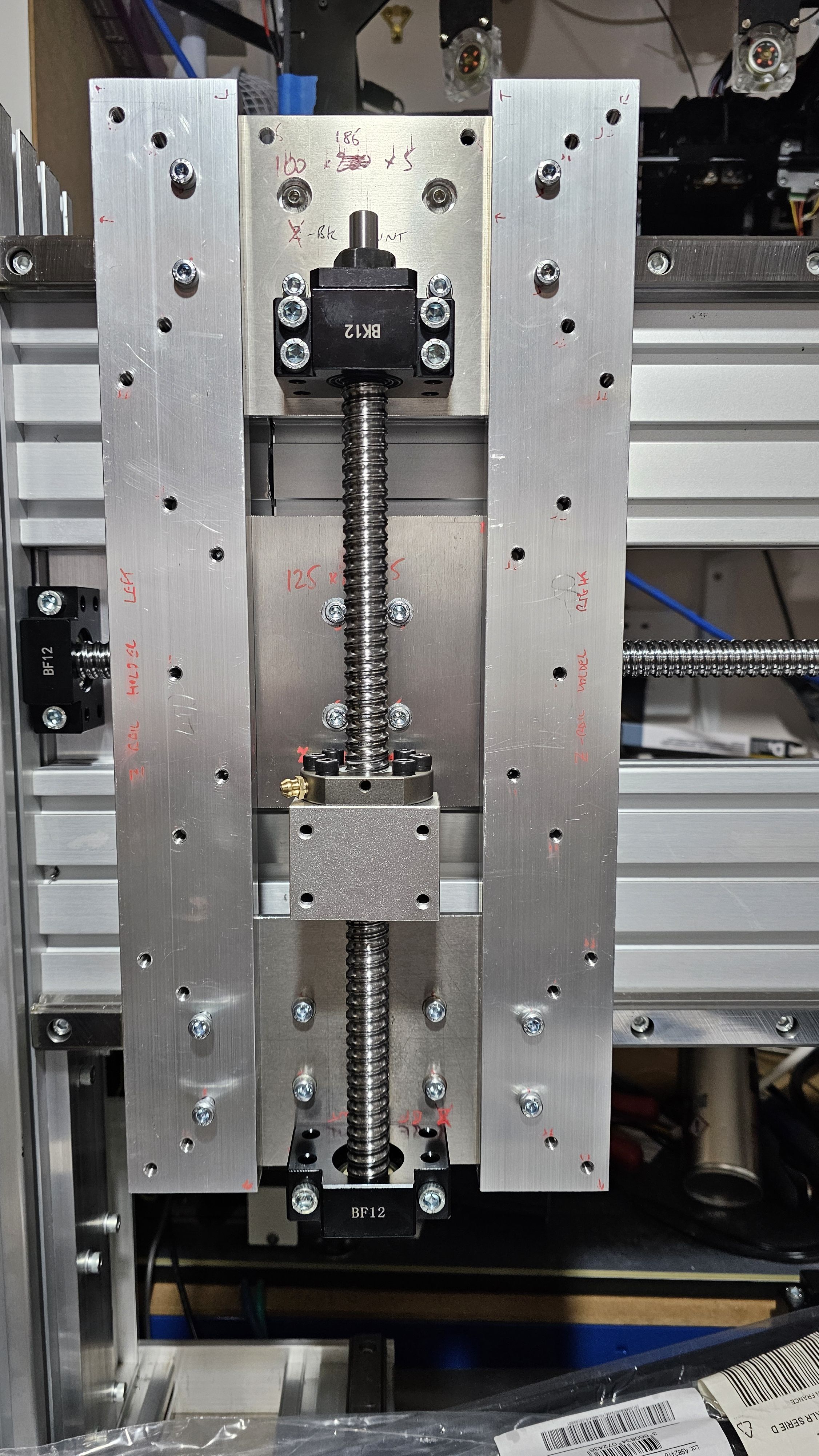
And with the Z-axis base plate:
Z-axis motor support
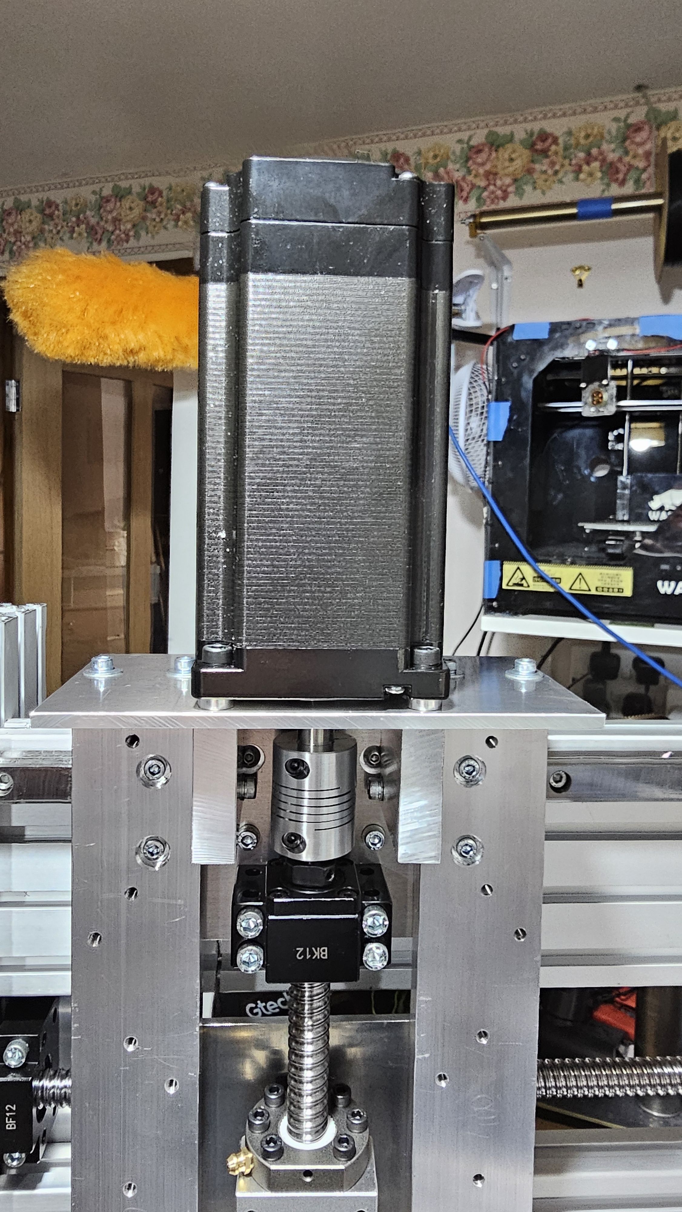
The Z-axis motor support had me stumped for a bit - I had modelled it to be 3D printed, but when I did it, I accidentally broke the heated glass bed of the printer. Machining it was an option, but it required a much better machine then CNC V4.
So I opted for a plate with some spacers:
Z-axis rails
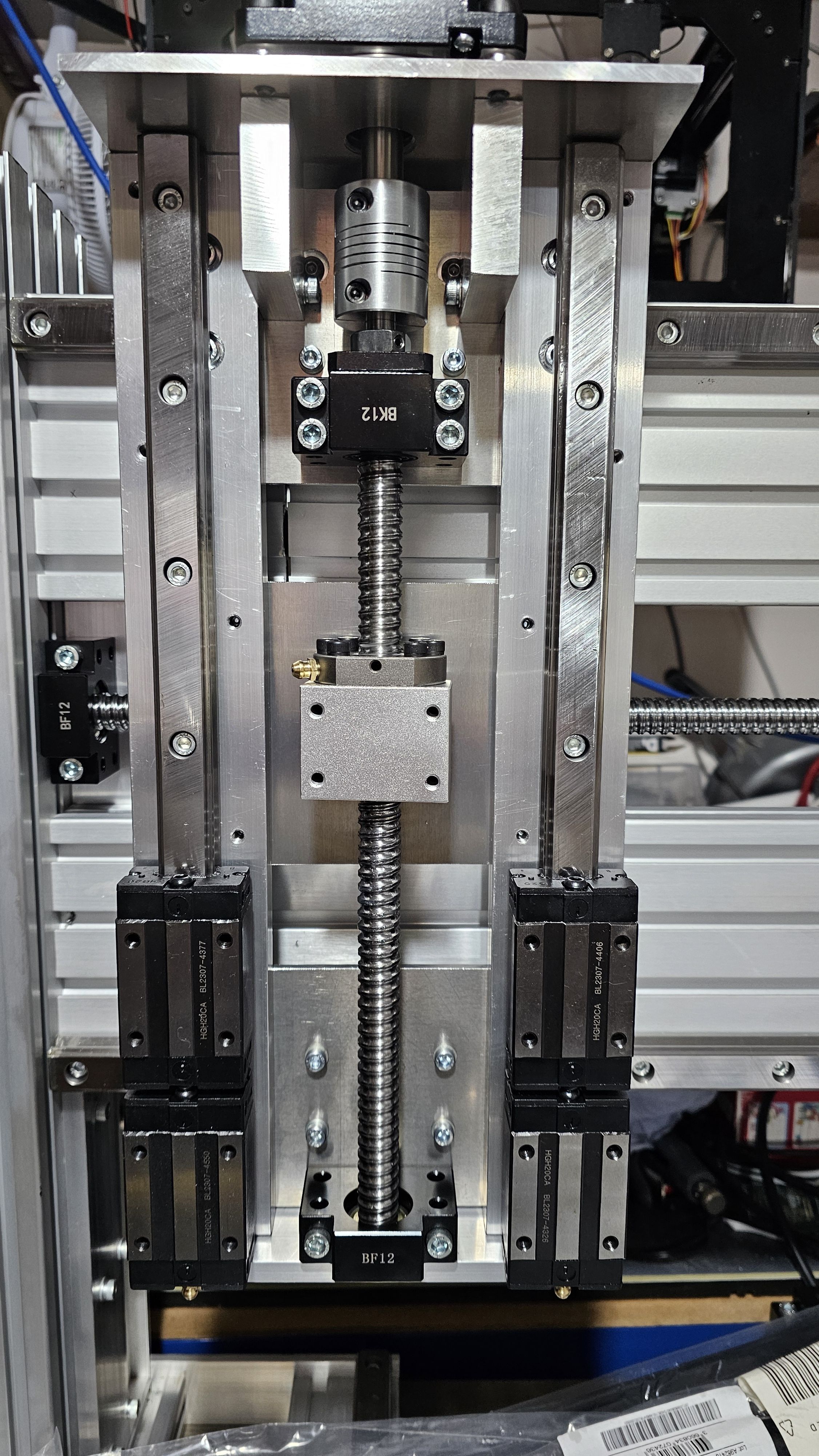
The Z-axis rails bolted into place, although I did need to machine some small pockets into the Z-axis base plate as they were slightly longer than the quoted dimensions!
Spindle mount
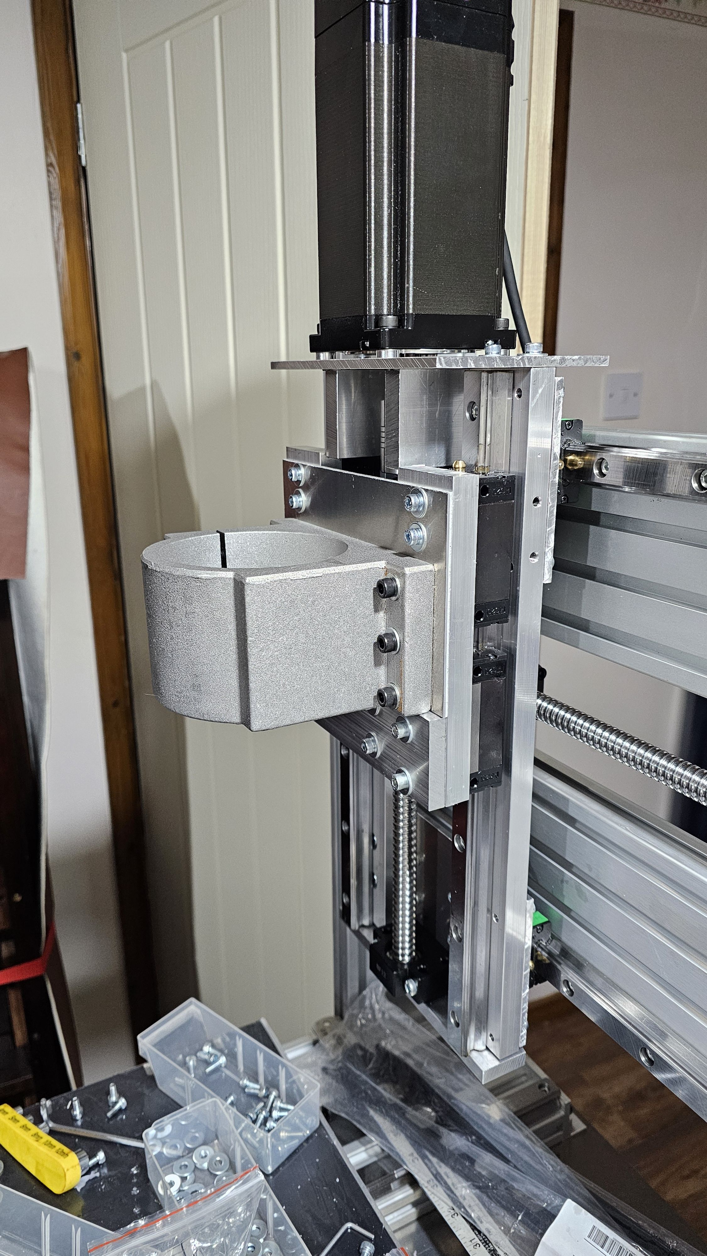
The spindle mount used a thin plate, and a thick bar to allow the spindle holder to be bolted to the Z-axis:
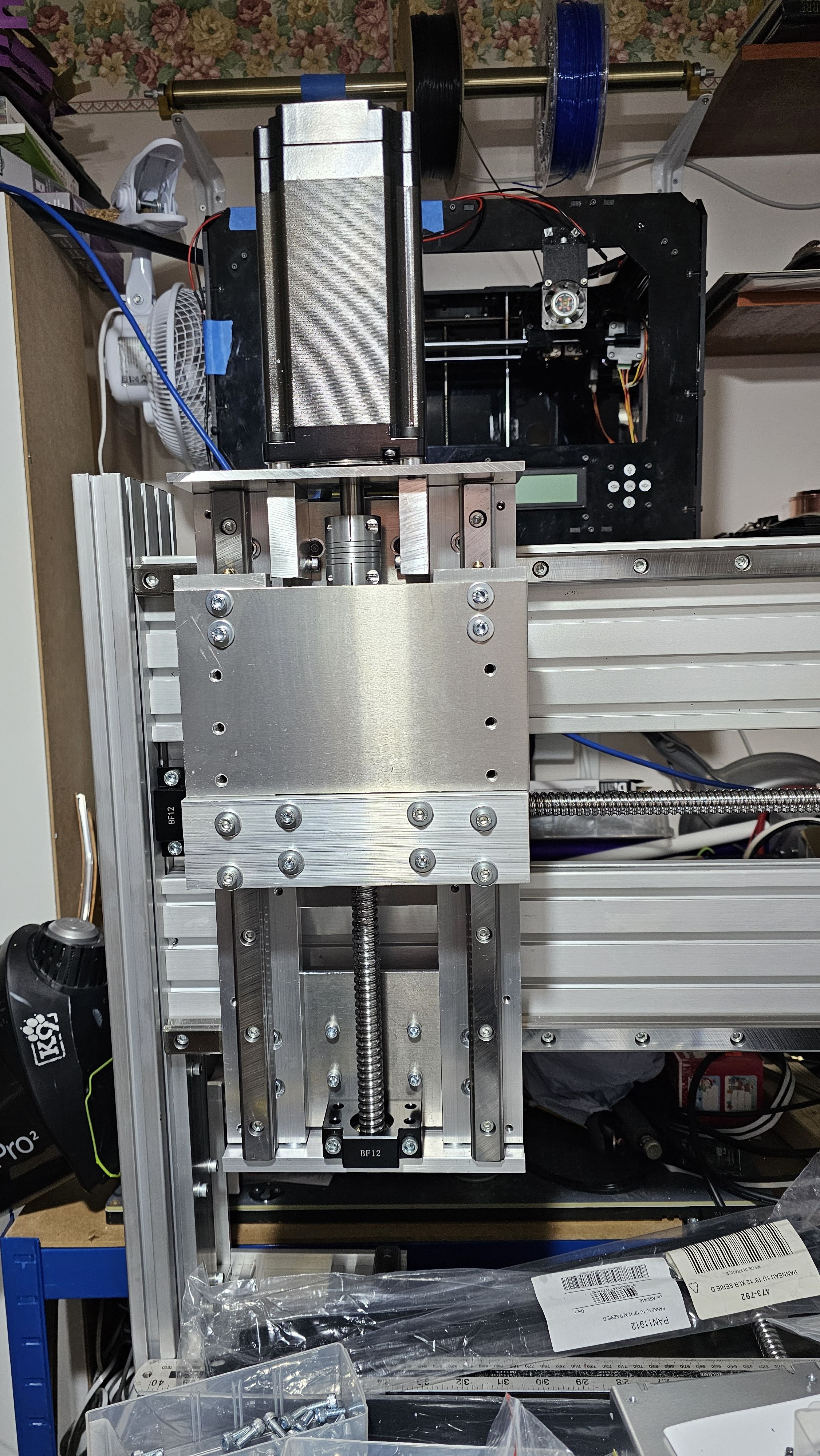
And with the spindle holder in place:
Spindle trial fitting
The spindle could now have a trial fit to make sure that there was enough clearance
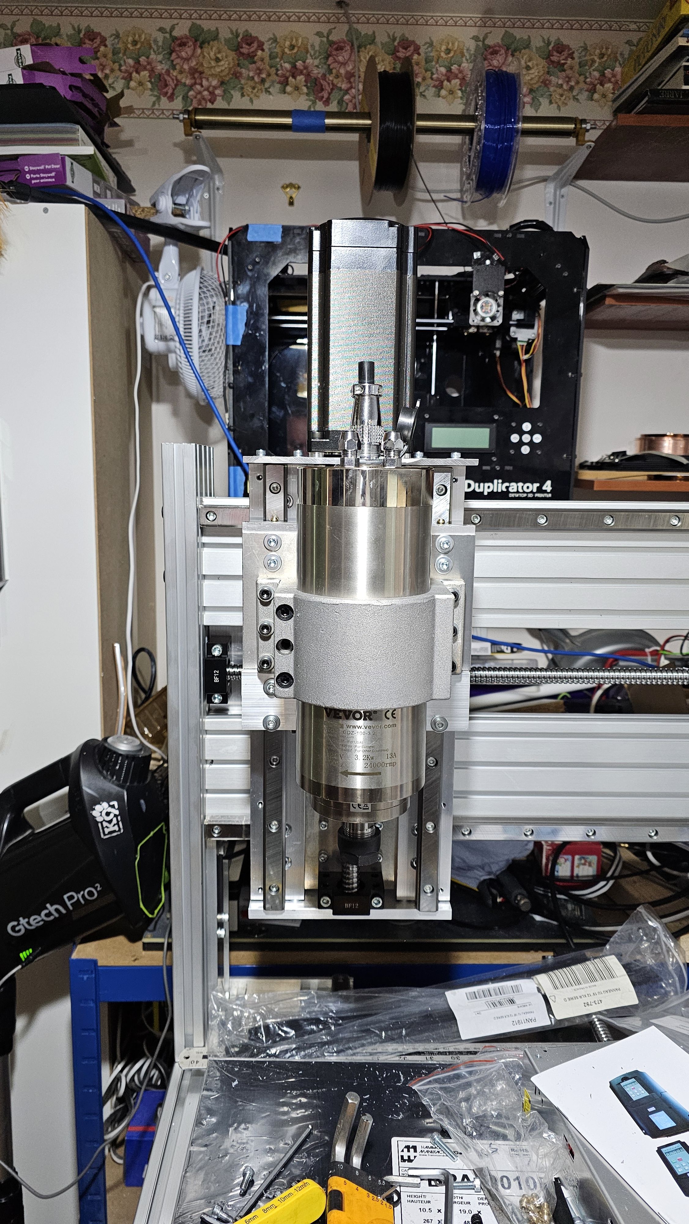
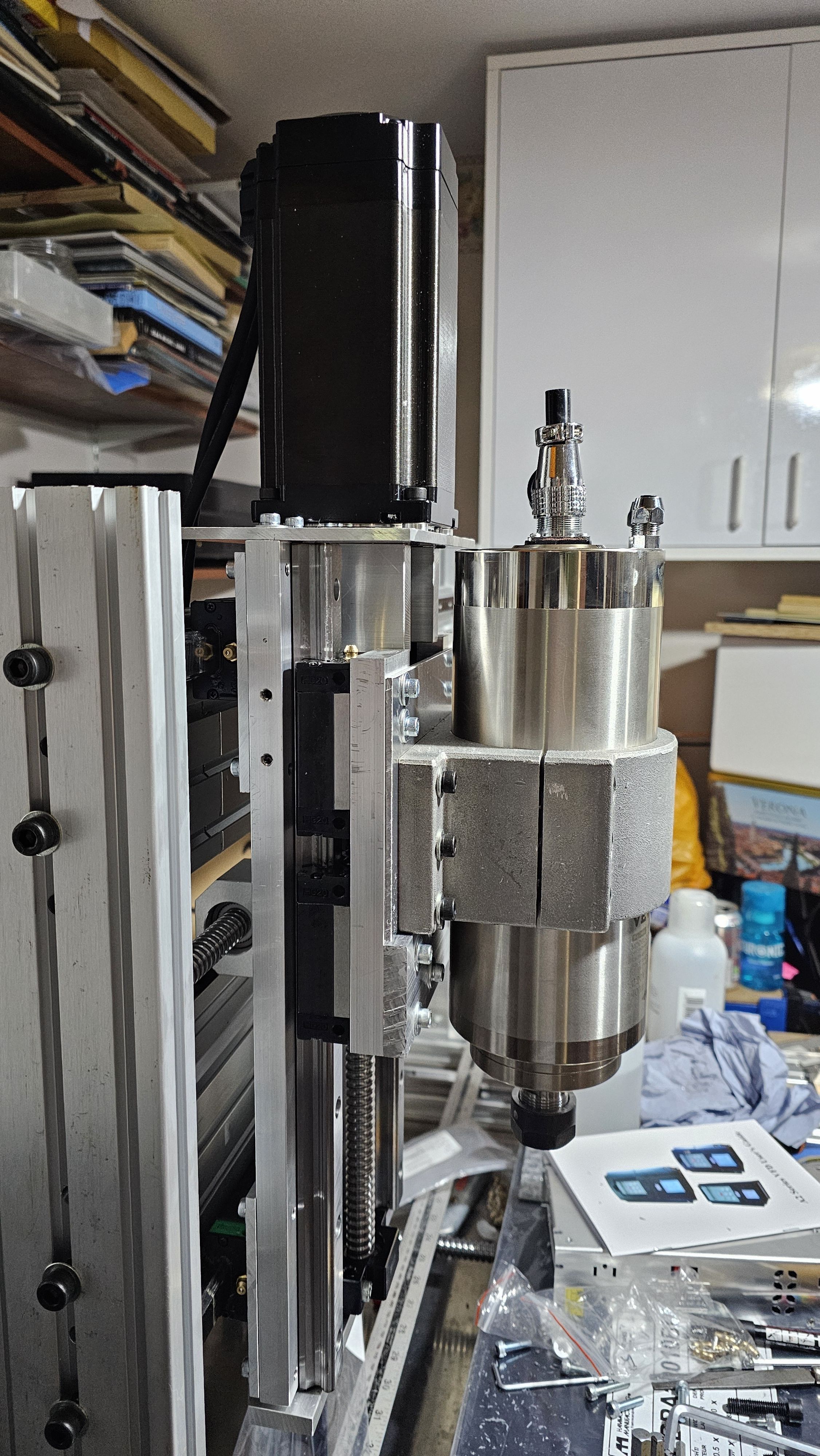
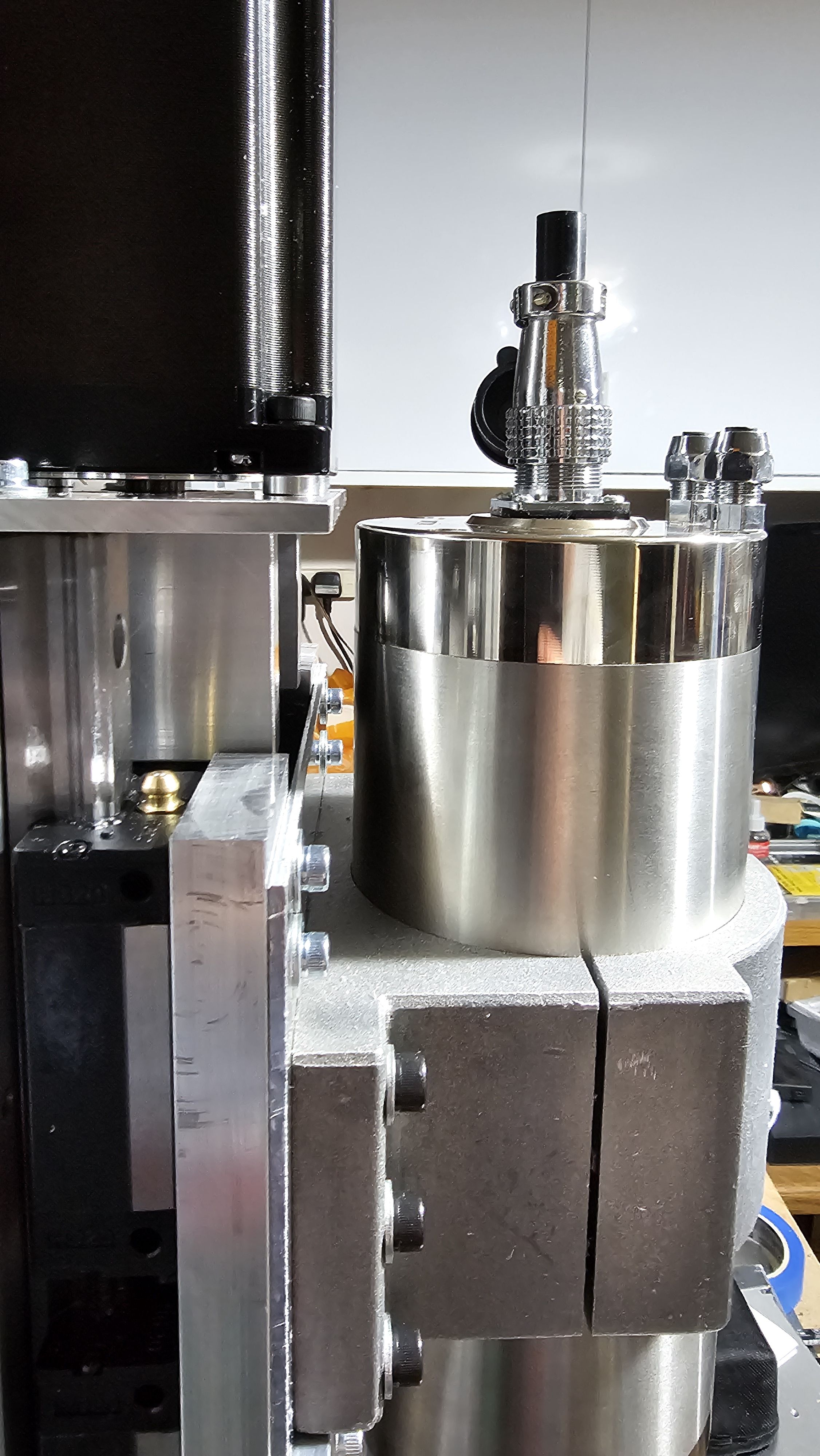
There is just enough space for the spindle to go past the Z-axis motor mounting plate...